IRSIM 9.7 Reference
Table of Contents
IRSIM Usage
Online IRSIM Tutorial
IRSIM Standard Command Set
Analyzer GUI Interface Commands
Statistics Package Commands
Connection-List Statistics Package Commands
Fault Simulator Package Commands
Power Estimation Package Commands
User Subcircuit Package
Random Number Generator Package Commands
The Analyzer GUI Interface
Using IRSIM With Tcl/Tk-Based Magic
Technology (.prm) Files for IRSIM Version 9.7
Documentation for IRSIM
Specifying X resources for IRSIM
Troubleshooting IRSIM
irsim [-s] [-p power_net]
[-g ground_net] prm_file sim_file ...
[+hist_file] [-tcl_file ...]
[-c tcl_file ...] [-@ cmd_file ...]
where the switches and arguments are as follows:
- -s
- If specified, 2 or more transistors of the same type
connected in series, with no other connections to their
common source/drain will be stacked into a compound
transistor with multiple gates.
- -p power_net
- If specifed, the net named power_net is assumed to be
the power supply. Simulation can be done without specifying
a power net, but any undeclared power net must be manually set
to logic one in the command file, and the time to parse the
netlist and start up will be increased.
- -g ground_net
- If specifed, the net named power_net is assumed to be
the ground return. Simulation can be done without specifying
a ground net, but any undeclared ground net must be manually
set to logic zero in the command file, and the time to parse
the netlist and start up will be increased.
- prm_file
- The electrical parameters file that configure the devices
to be simulated. It defines the capacitance of the various
layers, transistor resistances, threshold voltages, and so
forth. If prm_file does not specify an absolute path
then IRSIM will search for the prm_file as follows
(in order):
- ./prm_file (in the current directory).
- ${CAD_ROOT}/irsim/prm_file
- ${CAD_ROOT}/irsim/prm_file
The name prm_file may or may not contain the usual
file extension ".prm".
- sim_file ...
- All file names not beginning with a '-' are assumed
to be sim (netlist) files. These are files in ".sim" format, a
flat description of a circuit's transistors and parasitic passive
devices (R and C). The name sim_file may or may not
contain the usual file extension ".sim".
Each netlist file is read in turn and added to the network database.
There is only a single name space for nodes, so
references to node "A" in different network files all
refer to the same node. While this feature allows one to
modularize a large circuit into several network files, care
must be taken to ensure that no unwanted node merges happen due
to an unfortunate clash in names.
- [-tcl_file ...]
- File names prefaced with a '-' are assumed to be command
files, text files which contain command lines to be processed in
the normal fashion. These files are processed line by line.
when an end-of-file is encountered, processing continues with
the next file. After all the command files have been processed,
and if an "exit" command has not terminated the
simulation run, IRSIM will accept further commands from
the command line.
- [-c tcl_file]
- This is an alternative syntax for specifying a command file.
It must occur on the command line after any
simulation (.sim) files. The alternative syntax allows
UNIX shell command-line completion of the name cmd_file,
which is disabled when the filename is connected to the
"-" in front of it.
- [-@ cmd_file]
- This is another alternative form that forces a command file
to be read using syntax that is backwards-compatible to
non-Tcl versions of IRSIM, in which the commands "set"
and "flush" are used, instead of their altered counterparts
in the Tcl interpreter environment, "setvector" and
"histflush". This usage is equivalent to starting IRSIM
without specifying a command file, then typing
"@ cmd_file" at the IRSIM prompt.
- [+hist_file]
- The hist_file is the name of a file created with the
dumph command (see below). If it is present, IRSIM
will initilize the network to the state saved in that file.
This file is different from the ones created with the
">" command since it saves the state of every
node for all times, including any pending events.
IRSIM commands and their syntax are as follows:
- <
- see restorestate
- <<
- see restoreall
- >
- see savestate
- !
- see querygate
- ?
- see querysource
- @ filename
- Read and execute simulation commands from the file filename.
This command works in a backwards-compatible mode that allows
files in the original command-file syntax to be read. The
obsolete commands "set" and "flush", which are incompatible
with Tcl syntax, are interpreted to mean "setvector" and
"histflush", respectively. To read command files using Tcl
commands "set" and/or "flush", use the Tcl command
"source" (see below).
- activity from [to]
- Report circuit activity in time interval from to
to, if specified, or the current simulation time,
if unspecified.
- addnode name
- Adds a new node named name to the IRSIM database.
This node is unconnected, but it can be driven to specific
states with the 'h', 'l', and 'u' commands, added to vectors,
and displayed in the analyzer. It is useful for generating
timed reference events in the analyzer, or to import simulation
events from another program.
- alias [nodename [nodealias ...]]
- print node aliases (if there are any). With one argument,
prints the aliases of node nodename (again, if there
are any). With two or more arguments, nodes named
nodealias will be connected in the database.
- ana node|vector
- shorthand for analyzera (see below)
- analyzer [-b|-o|-d|-h]
node|vector...
- display node/vector(s) in the analyzer window. This command
causes the analyzer window to be initialized and displayed
if it was not already created; otherwise, the indicated node
or vector is added to the display. If the signal name is a
vector, then the option switches force that signal to be
displayed in the indicated numeric base ("-b" for binary,
"-d" for decimal, "-o" for octal, and "-h" for hexidecimal).
- assert node|vector [mask] val
- Assert that the indicated node or vector is equal to
value val after bit-masking with mask.
- assert node
- Short form. Without an assertion, returns the value of node
node. This can be used directly in conjunction with
magic to query the simulation value of nodes without
adding them to the watch or display lists. To return the
value of a layout node, select paint and do (verbatim):
assert [getnode]
- assertWhen nodeT valT node val
- assert that the value of node is equal to val
upon the condition that node nodeT switches to
value valT
- at [+]time { procedure }
- (command introduced in IRSIM version 9.7.32)
Schedule the command or set of commands "procedure"
to be executed at time time (in nanoseconds). In
the Tcl/Tk version of IRSIM, procedure may be any
valid set of Tcl commands or IRSIM commands. The procedure
is executed exactly once, at the specified time. If the
time value is preceded by "+", then the time
is interpreted as a time relative to the current simulation
time. In the Tcl
version of IRSIM, the at command returns a unique
ID for the event that can be used for the cancel
and get options (see below). Also see the command
every.
- at get|cancel id
- (command introduced in IRSIM version 9.7.32)
The get option returns the procedure associated with
the scheduled event whose identifying (integer) tag is
id. The cancel option cancels the scheduled
event whose identifying tag is id.
- back time
- move simulation time back to specified time
- c [n]
- simulate for n clock cycles (default 1)
or continue last simulation command prior to stopping.
Use of this command requires that a clock has been
defined using the "clock" command.
- changes from [to]
- print nodes that changed in the indicated time interval
- clear
- remove all signals from analyzer window
- clock [node|vector [val]]
- define a clock bit sequence for the indicated node or
vector. This clock signal will then define the actions
that occur when either the "c" (clock) or
"p" (phase) commands are issued.
If the clock is defined by a vector, then val
is a binary string equal to the length of the vector.
The prefix "0b", "0d", "0o", or
"0h" may be used to specify the value in
(respectively) binary, decimal, octal, or hexidecimal.
- d [node|vector]...
- print node/vector(s) or the entire display list
- debug [options]
- print/set debug state (? for help)
- decay [value]
- set a time limit for undriven nodes to become indeterminate.
Otherwise, undriven nodes retain their value prior to becoming
undriven, indefinitely. This helps identify problems where
dynamic logic is not properly refreshed. A value of 0
(zero) indicates no decay (and is the default value).
- display [[-]option]
- Set or reset display modes. option may be one of the
keywords cmdfile, automatic, or tclproc.
When the keyword is prefixed with "-", the display
mode is disabled; otherwise, it is enabled.
- cmdfile
- When this option is on, commands read from a command file
are echoed before they are executed. Default is off.
- automatic
- Print out the current display list (see the "d"
command) after execution of "s" or "c"
commands. Default is on.
- tclproc procedure
- This option declares a Tcl procedure to be executed
whenever a node on the display list is displayed.
The procedure will be passed, in order, the arguments
nodename, bitstring, and time.
The procedure must also handle the time signature
passed at the end of the watchlist, which takes
the same form, with nodename = "time"
and bitstring = "t". The procedure
may choose to ignore any arguments. The Tcl procedure
may be removed by passing a null string ("")
as the procedure.
- dumph [file]
- write network state history to file
- every interval [start]
{ procedure }
- (command introduced in IRSIM version 9.7.32)
Schedule the command or set of commands "procedure"
to be executed every interval nanoseconds. In
the Tcl/Tk version of IRSIM, procedure may be any
valid set of Tcl commands or IRSIM commands. The
procedure is first scheduled to execute at the current
time plus interval, unless start is specified,
in which case the procedure will be first scheduled to
execute at (absolute) time start (nanoseconds).
After each execution, the command is rescheduled at
interval nanoseconds later. In the Tcl version of
IRSIM, the at command returns a unique ID for the
event that can be used for the cancel and get
options (see below). Also see the command Also see the
command at.
- every get|cancel id
- (command introduced in IRSIM version 9.7.32)
The get option returns the procedure associated with
the scheduled event whose identifying (integer) tag is
id. The cancel option cancels the scheduled
event whose identifying tag is id.
- exit [status]
- exit program with given status (default: 0)
- flush (obsolete)
- see histflush
- h node|vector...
- drive node/vector(s) to 1 (high)
- has_coords
- print YES if transistor coordinates are available
- help [command]...
- print info on command(s) or available commands
- hist [on|off]
- display or set history collection mode
- histflush [time] (formerly flush)
- flush history up to time time (default: now).
The beginning of the dataset is reset to the indicated
time value.
- inputs
- print currently driven (input) nodes
- ires [time]
- print/set incremental resolution to time
- isim [file]
- read changes from file and incrementally resimulate
- l node|vector...
- drive node/vector(s) to 0 (low)
- listnodes
- This function returns a list of all the nodes in the
(flattened) circuit. IRSIM version 9.7 Revision 4 and
newer make use of this to enable a "signal manager"
window displaying all traces and allowing traces to
be added to or removed from the analyzer display.
- listtopnodes [separator]
- This is a Tcl procedure defined in the Tcl version
of IRSIM. It assumes that the simulation netlist was
derived from a flattened hierarchical circuit description,
and that the node names follow a naming convention of:
instance/instance/.../node
Top-level nodes are those that contain no slash separators.
The procedure simply calls the "listnodes" function
(see above) and returns the subset of names that do not
contain slashes. The separator is optional; if
specified, the given separator character or substring will
be used to identify hierarchical nodes in place of the
slash character.
- listvectors
- This function returns a list of all the vectors that
have been defined in the simulation.
- logfile [[+]file]
- start/stop log file (+file appends to file)
- model [linear|switch]
- print/change simulation model
- p
- step clock one simulation step (phase). This command
requires that a clock has been defined using the
"clock" command.
- path node|vector...
- critical path for last transition of node(s)
- print [text...]
- print specified text
- printp [n]
- print up to n pending events (default: all)
- printx
- print all undefined (X) nodes
- q
- terminate input from current stream
- query node|vector
- Tcl version only. Returns the (decimal) value of node
node or vector vector. The returned value is
a Tcl object, as opposed to the assert short form,
which is simply printed to stdout.
- querygate node (formerly !)
- print information about a node's gate connections
- querysource node (formerly ?)
- print information about a node's source and drain connections
- R [n]
- simulate for n cycles (default: longest sequence)
- readh file
- read network state history from file
- readcver name
- Read a verilog dump file. This is a Tcl script that makes use
of the "addnode" command to generate one node per signal,
then schedule events as marked in the file, and simulated through
those events.
- readsim [prefix] name
- Read a .sim format file. IRSIM has the capability to
read multiple files and simulate all of them simultaneously.
The prefix option creates a unique namespace for each
file read in, so node names common to two files are not merged
in the IRSIM database.
- relax [l|h|r]
- Attempt to resolve undefined nodes by forcing an initial
condition (low logic value) on all undefined nodes. These
conditions are applied instantaneously, e.g., like an "l"
command, but the logic value state is not persistant. This
command usually suffices to resolve nodes that are undefined
due to a logical feedback loop. Since this command will
obscure truly undefined nodes, it should be used with caution,
and only as a last resort. Option "l" forces all
undefined nodes to a low logic value. Option "h"
forces them to a high logic value, and option "r"
randomly selects a high or low logic value for each undefined
node encountered.
- report [args]
- print/set trace-info or decay report (? for help)
- restorestate filename (formerly <)
- restore the network state from the indicated file
- restoreall filename (formerly <<)
- restor the network state and the value of all inputs from
the indicated file.
- s [time]
- simulate for specified time (default: stepsize). time
is in nanoseconds.
- savestate filename (formerly >)
- write the current network state to the indicated file.
- set (obsolete)
- see setvector
- setlog [file|off]
- print/change net-changes log-filename
- setpath [[+] path]...
- print/set/add-to cmd files search path
- settle [value]
- set a minimum time for multiply-driven nodes to become
indeterminate. Otherwise, nodes driven by conflicting
values become indeterminate based on RC time constant
calculations, which will be much too fast, as the
condition is primarily controlled by second-order effects.
Setting a "settle" value helps prevent propagation of
indeterminate values in circuits with pass-transistor
logic or back-to-back inverters in delay flip-flops. A
typical value is normally less than one step size.
value is a real-valued number, and is interpreted
as nanoseconds.
- setvector vector value (formerly set)
- Set the value of vector vector to value.
value is a binary string equal to the length of the
vector. The prefix "0b", "0d", "0o",
or "0h" may be used to specify the value in
(respectively) binary, decimal, octal, or hexidecimal.
Also, for backwards compatibility with some IRSIM version
of unknown origin, the prefixes "%b", "%d",
"%o", and "%h" (and equivalently, "%x")
are also accepted at valid syntax. Negative numbers can
be entered as, for example "-0d1" and will be
translated into a 2's complement binary number with respect
to the bit length of the vector being set. For instance,
if A is a binary vector of length 4 bits, then
"setvector A -0d1" will set A to the binary
value 1111. The notation "0x" is allowed
for hexidecimal, although be aware that "0x" is
also a valid binary setting (first bit forced to zero,
second bit released from forced input). Thus "0x0
is a correct binary setting for a vector of size
three bits, or a correct hexidecimal setting for
a vector of any other size.
- source
- This is the Tcl "source" command, and can be used to read
and execute any IRSIM file that contains any mixture of
Tcl-compatible IRSIM commands and Tcl/Tk commands. This
means that the file must not use the incompatible command
names "set" and "flush", which have been replaced by
"setvector" and "histflush".
- start [-s] param_file sim_file
- Because IRSIM is a Tcl package, it has an initialization
function, which runs automatically upon loading, and a
separate function which starts the simulator. This
allows IRSIM to be loaded and ready to go before having
a ".sim" file ready for input. The start command
takes the same syntax as the standalone UNIX command
prompt irsim command.
- stats
- print event statistics
- stepsize [time]
- print/set simulation step size (nanoseconds).
- stop [-]node|vector...
- pause simulation when node/vector(s) change
- t [-]node|vector...
- start/stop tracing specified node/vector(s)
- tcap
- print all shorted transistors
- time [command...]
- time given command or program
- toggle node|vector...
- toggle the logical value of a node from 0 to 1 or 1 to 0.
For vectors, toggle each bit of the vector independently.
Bit values which are undefined are not changed (command
introduced in version 9.7.32)
- u [node|vector]...
- drive a node/vector(s) to X (undefined)
- unitdelay [time]
- force transitions to specified time (0 to disable)
- until node|vector [mask] val count
- simulate until the condition node or vector,
optionally masked with mask is equal to value val.
- V [node|vector [val...]]
- define input sequence for a node or vector. For vectors,
val is a binary string equal to the length of the
vector. The prefix "0b", "0d", "0o",
or "0h" may be used to specify the value in
(respectively) binary, decimal, octal, or hexidecimal.
- vector name node...
- (re)define vector named name composed of indicated
node(s). As an aid to typing long lists of nodes and
to aid compatibility with verilog, it is possible to type
node in verilog vector notation, e.g., M<1:8>,
under the condition that nodes M<1> through
M<8> exist and that "M<1:8>" itself
is not a named (single) node. Otherwise, wildcard characters
are not allowed in the list of nodes since the order of the
nodes cannot be determined. If a vector is redefined, any
attributes of the original vector (e.g., being on the display
or trace list) are lost.
- w [-]node|vector...
- add/delete node/vector(s) to display-list
- when nodeT valT
{ procedure }
- execute the procedure procedure on the next
occurrence of the condition that node nodeT
switches to value valT. valT may be
a concatenated list of types; e.g., "lh" will
execute on either a rising or falling edge of
nodeT.
- whenever nodeT valT
{ procedure }
- execute the procedure procedure on every
occurrence of the condition that node nodeT
switches to value valT. valT may be
a concatenated list of types; e.g., "lh" will
execute on both rising and falling edges of nodeT.
The whenever command returns an integer tag
value that can be used to track the procedure (see below).
- whenever get|cancel id
- The get option returns the procedure associated with
the scheduled event whose identifying (integer) tag is
id. The cancel option cancels the scheduled
event whose identifying tag is id.
- wnet [file]
- write network to file (smaller/faster than sim file)
- x node|vector...
- make node/vector(s) undriven (non-input)
- Xdisplay [Xserver]
- print/set X display (for analyzer)
The original "analyzer" graphics display was not associated
with any command-line interface commands. This situation
was rectified, by necessity, to enable the use of the
analyzer and GUI under Tk. The commands are as follows:
- base get|set [trace] [base_type]
- Set or query the numerical base for printing vector values
on the trace. Valid base_type names are: binary,
octal, decimal (unsigned decimal), signed
(signed decimal), and hexidecimal. Signed values are
in 2's complement notation with respect to the length of the
vector. Values other than binary are valid for vector lengths
up to 64 bits.
- marker [1|2] option...
- Set or change the position of the two vertical markers.
Valid options are:
- get
- Get the marker position
- set trace time
- Set the marker to mark signal trace
at time time
- move time
- Move the marker to time time
- off
- Turn off the selected marker
- print option...
- Handle printing options, which are as follows:
- banner [on|off]
- If true, print the title (see below) as a header
on the output page.
- file filename
- Print a PostScript version of the screen to
the indicated file named filename.
- legend [on|off]
- If true, print a legend of each trace on a second
output page (off by default).
- outline [on|off]
- If true, print an outline box around the output
graph.
- times [on|off]
- If true, print simulation times along the X axis
of the output graph.
- title string
- Set the title for the page banner to the string
string. This also changes the title of the
analyzer window, displayed in the upper left-hand
corner.
- simtime option...
- Report or set the time value for various points in the
analyzer window. Valid options are:
- begin
- Report the time value of the start of the dataset. Normally
this is zero, unless the histflush command has been
issued.
- end
- Report the time value of the end of the dataset, which is the
current simulation time.
- left [value]
- Return the time value represented by the left edge of the
analyzer window. If value is given, then adjust the
analyzer window view so that the left edge is at the indicated
time.
- right [value]
- Return the time value represented by the right edge of the
analyzer window. If value is given, then adjust the
analyzer window view so that the right edge is at the indicated
time.
- delta
- Return the time span represented by the distance between the
edges of a split marker.
- marker
- Return the time represented by the horizontal position of the
vertical marker (if it is active).
- cursor
- Return the time represented by the position of the mouse
pointer in the analyzer display window.
- move [+|-]value
- Move the analyzer display view so that the value value
is positioned at the left edge of the window. If a plus or
minus symbol is given before value, then value
is treated as a time relative to the current time at the
left edge of the window.
- scroll [on|off]
- Set or report the status of auto-scroll. When auto-scroll
is on, the analyzer display updates every simulation
timestep to set the current simulation time at the right
edge of the display window. Note that even when auto-scroll
is active, if the current timestep is outside of the window
display prior to the simulation step, then the window view
will not be updated.
- trace option...
- Add, modify, or remove a trace from the analyzer.
Valid options are as follows:
- top name
- Return the pixel Y value of the top edge of the indicated
trace in the analyzer display window.
- bottom name
- Return the pixel Y value of the bottom edge of the indicated
trace in the analyzer display window.
- order name
- Return the order (numbered from zero, the trace at the top
of the window) of the indicated trace.
- base [name] [value]
- Return or set (if value is given) the numeric base
used to display the value of a vector. Known values are
binary, octal, decimal, and
hexidecimal.
- class name
- Return the class (which is either "node" or "vector") of
the indicated trace.
- cursor [value]
- Return the name of the trace which is closest to the pixel
Y position value. If value is not given,
then return the name of the trace that is closest to the
mouse pointer position. If no trace is near the indicated
value or pointer position, then nothing is returned.
- input name
- Indicate whether the value of name (or each bit,
individually, if name is a vector) is a driven
(input) signal or not. Driven bits are returned as
value "i", and undriven bits are returned as value
"-".
- list all|nodes|vectors
- Return a list of traces displayed in the analyzer. This
can be either a list of all traces, or it can be restricted
to list only those traces that are nodes or those that
are vectors.
- select [name]
- Set the currently selected trace to be the trace indicated
by name. If no trace name is given, then return
the name of the currently selected trace, if any.
- value name
- Return the instantaneous value of the trace named
name at the time represented by the vertical
marker. If the marker is not active, then nothing is
returned.
- bits name
- Return the number of bits in the trace indicated by
name. If name is a node and not a vector,
then the result is always 1.
- remove name
- Remove the trace named name from the analyzer display.
- characters [value]
- Limit the number of characters displayed for each trace name
on the left side of the display to the integer number
value. This prevents long hierarchical names from
dominating the analyzer display window. If no value
is given, then the current limit value is returned. The
default character limit is 15.
- move name1 name2
- Swap the relative positions of traces name1 and
name2 in the analyzer window.
- zoom [in|out]
- Change the time span of the window view, effectively
zooming the time axis in or out.
If the "stats" packages has been compiled in (normally true), then
the following additional commands are available:
- histev [clear|off|on]
- enable/disable/clear event activity record
- evstats [file]
- print event activity recorded
If the "cl statistics" packages has been compiled in (normally
true), then the following additional command are available:
- clstats [file]
- print connection-list statistics
If the "fault simulator" package has been compiled in (normally
true), then the following additional command is available:
- faultsim infile [outfile]
- do stuck-at fault simulation
If the "power estimation" package has been compiled in (normally
true), then the following additional commands are available:
- powlogfile [[+]file]
- start/stop power logfile (+file appends to file).
Typically, this is called as "powlogfile /dev/null"
to redirect output, as the power summary and histograms
are more useful than the per-step output.
- powtrace [-]node|vector...
- start/stop power tracing specified node/vector(s).
The node string can be wild-carded. Typically,
this is called as "powtrace *" to enable power
calculations on all nodes.
- sumcap
- print out sum of capacitances of all nodes.
- power node
- specify that the node named node is a power supply
node. All power and ground nets must be specified for the
power estimation to work correctly. Note that specifying
a net as a power supply is not sufficient to set the
network as logic high. The net net must be specifically
set to logic high with the command "h node".
Multiple nodes can be declared power supplies.
- ground node
- specify that the node named node is a ground return
node. All power and ground nets must be specified for the
power estimation to work correctly. Note that specifying
a net as a ground return is not sufficient to set the
network as logic low. The net net must be specifically
set to logic low with the command "l node".
- vsupply [net] [value]
- Set supply voltage = value Volts. The net gives
the name of the power supply net. Multiple power supplies
with different values can be specified.
- powstep
- Toggle display of power estimate for each step. Note that
this command is mutually exclusive with powhist.
- powhist init min max [buckets]
- Initialize power calculation histogramming. The histogram
method is mutually exclusive with powstep. The
histogram data is taken over buckets bins with the
first bin at power value min and the last bin at
power value max. Values for min and max
are given in milliwatts.
- powhist capture|print|reset
- Once power histogramming is enabled, data are analyzed
using the following command options:
- powhist capture
- IRSIM accumulates power data (total switching energy)
on every device every time the device switches, resulting
in a total value of energy expended in the system.
The capture option divides the energy by the
time over which data have been accumulated, arriving
at a power value (total energy divided by the time
interval). The resulting power value is histogrammed
according to the histogram values specified in the
powhist init command option, and the energy
values are reset to zero. Typically, this command
option is called once per clock cycle, so a typical
setup would be to declare "every time
{powhist capture}" and set time to the
clock period, resulting in a histogram of clock
cycle power.
- powhist print
- This command option prints the histogram data, with
one histogram bin per line, with three entries
being the bin starting value, the bin ending value,
and the number of entries within the bin.
- powhist reset
- This command resets the histogram data and terminates
the collection and histogramming of power data.
- powquery
- This command returns the current calculated value of the total
power, which is the total accumulated energy divided by the
time interval since the use of powstep, powhist
init, or powhist capture, for the nodes specified
by the powtrace command.
IRSIM can implement arbitrary circuit components, not just the
internally-defined transistors, resistors, and capacitors.
Subcircuits can be defined and used in the ".sim" file with the
syntax:
x input1... [output1]... [options]
subcircuit_name
This line defines a subcircuit named subcircuit_name that
connects to a list of input and output nodes starting
with input1. The remaining arguments options may
be anything, although it is recommended that they be restricted
to "key=value" pairs defining parameters used by
the subcircuit.
There are three different ways to define user subcircuits in IRSIM.
Two of them involve defining the subcircuits in precompiled C code.
This requires that C routines be created for all subcircuits
needed.
The first of the two pre-compiled methods is the original one, and
results in a special version of the IRSIM executable that understands
these definitions. For the non-Tcl-based IRSIM, this is the only
choice for making user-defined subcircuits. See the source
distribution's "usersubckt" subdirectory for examples of code
defining compiled-in subcircuits.
All subcircuit definition methods are available with the Tcl-based
version of IRSIM, although the method mentioned above is
deprecated in favor of the second method. In the second method,
a file of C routines defining a library of subcircuit components
is required, and it is compiled as a shared-object library. The
shared-object library can then be loaded at run-time. This method
makes it possible to maintain a set of different libraries for
different projects. Note that the shared-object library must
be loaded prior to any .sim-format file containing instances of
the subcircuits defined in that library. A convenient way to
handle this is not to read the .sim file from the OS
command line, but to load the shared-object library and load the
.sim file (in that order) from either the command file script
or the IRSIM command line, after startup:
# Tcl command file script for IRSIM
load /usr/local/lib/irsim/tcl/diglib.so
readsim mysimfile.sim
The tclsubckt subdirectory of the IRSIM source has an
example file, diglib.c, containing examples of
digital standard cells defined C code routines. Each subcircuit
requires an evaluation function, and optionally an initialization
function.
The third method of defining a subcircuit is slower but
does not require any compilation. To do this, simply define all
subcircuits as procedures in Tcl at startup. This can be done
in a similar way to the manner mentioned above, in which IRSIM
is started without loading the .sim file, then the command file
script defines all the necessary subcircuits before loading the
.sim file with the "readsim" command. Each subcircuit
requires two procedures, an initialization procedure and an
evaluation procedure. The syntax of these procedures is
defined below:
proc subcircuit_name_init {} {
procedure_body
}
proc subcircuit_name_eval {
instr outstr udata } {
procedure_body
}
The initialization procedure takes no arguments. It must return
a list of values describing the circuit. This list consists of,
in order:
- num_inputs
- An integer declaring the number of input nodes in the subcircuit.
Every circuit must have at least one input node, even if it is
just a "dummy" node used to force evaluation of the subcircuit.
A subcircuit is only evaluated when one of its inputs changes
state.
- num_outputs
- An integer declaring the number of output nodes in the subcircuit.
A subcircuit may legally have zero outputs (the subcircuit may
only be producing diagnostic output, or communicating with
another tool).
- res_list
- A list of (num_outputs * 2) real-valued numbers. The
first half are the values of the pull-up transistor "on"
resistance of the subcircuit's output driver pFET, one value
per output. The second half are the values of the pull-down
transistor "on" resistance of the subcircuit's output driver
nFET, one value per output. All values are in Ohms. If the
circuit has no outputs, this term should be an empty list
("{}").
- user_data
- This term is optional and may contain any data whatsoever.
user_data is a single value, however, so multiple
values in the data should be collected together into a
list. A unique instance of this value is saved for each
instantiated subcircuit. It is passed directly to the
evaluator procedure, which may modify it. Since the user
data is a Tcl list, the evaluator procedure may modify the
list directly using Tcl commands like "lreplace".
This allows each subcircuit instance to maintain internal
states. If an "x" record in the .sim file has
parameters between the last I/O node and the subcircuit
name, those parameters will be appended to the user_data
list for the instance, and should be handled by the
evaluator procedure (see below).
The evaluator procedure will be passed the two strings "instr"
and "outstr", which are the values of the input and output pins,
in character form ("x", "0", and "1"). If the initialization procedure
returned a non-NULL value for user_data, and/or the instance
record in the .sim file contained extra parameters, then this value will
also be passed to the evaluator procedure. The evaluator procedure
must return a list containing the following values:
- newoutstr
- This is a string containing character values for each of the
output nodes. The characters may be from the set "0", "x",
"z", and "1", and also "l" and "h", case insensitive.
- delays
- This is a list of real-valued numbers representing the delay
to each of the outputs. Note that if the outputs have
different delays relative to different inputs, it will be
necessary for the subcircuit to maintain an internal
representation of the previous state of all inputs, and
determine which delay value is appropriate. Also note that
the output nodes are given no capacitance, so the delay
value should include any transition delay in the outputs
due to charging their own capacitance.
For example, the procedure defining an inverter might look like:
	proc inverter_init {} {
	    # Inverter is 1 input, 1 output, 500 ohms "on" resistance
	    return {1 1 {500.0 500.0}}
	}

	proc inverter_eval {in out ulist} {
	    # Inverter delay is 10ps.  ulist is not used.
	    switch -- $in {
	        0 {set rval 1}
	        1 {set rval 0}
	        default {set rval x}
	    }
	    return {$rval 10}
	}
Procedures for most combinatorial logic are conveniently implemented
as logic tables using the Tcl switch statement, particularly
simple when using the -glob option with wildcard characters.
The return delay value is given in picoseconds. There is no limit on
the number of subcircuit procedures that may be defined.
Important note: The .sim file syntax for subcircuits shown
above has been changed from the original IRSIM user subcircuit
definition, and is not backwardly-compatible. Old user-defined
subcircuits need to be rewritten to accomodate the new syntax by
removing the "number of inputs" and "delay" parameters from the
.sim file and putting them in the subcircuit definition tables in
the source code.
The Tcl/Tk-based version of IRSIM comes with a separate Tcl
package extension that creates the Tcl command "random",
which is based on the C stdlib "rand48" routines.
The package itself is general-purpose and can be run independently
of IRSIM. In any "wish" or "tcltk" interpreter environment, run
the command "load /usr/local/lib/irsim/tcl/random.so" to
load and initialize the package. Within IRSIM, this package is
loaded automatically. Within IRSIM, the most helpful use of the
package is the "random -bitstream n" option, to
generate uniformly random input vectors into a circuit. For
example:
setvector A [random -bitstream 16]
will set the vector A to a random value of 16 bits.
The package creates a single new command "random" whose
options are as follows:
- no arguments
- Returns a number taken uniformly from [0..1)
- -reset
- Reseeds the generator using a combination of the
current process ID and current time.
- -seed n
- Reseeds the generator with the specific seed value n.
- -integer [a [b]]
- Generates a uniformly-distributed random number in the
indicated range (see below), and returns the value
rounded down to the largest integer less than or equal
to the floating-point value. By default, the number returned
is within the full range of a 32-bit signed integer. With option
"random -integer a", the number returned will
be between -a and +a. With option "random
-integer a b", the number returned will be
between a and b. The routine is capable of
returning numbers up to 64 bits unsigned.
- -bitstream [n]
- will generate a uniform random binary value of length n.
The value returned is in string form, with effectively
unlimited length. By default, the number returned is
a 32-bit value (32-character string).
- -normal m s
- Returns a floating-point value taken from a gaussian distribution
with mean m and standard deviation s.
- -exponential m
- Returns a floating-point value taken
from an exponential distribution with mean m.
- -uniform a b
- Returns a floating-point value taken
taken from uniform distribution on [a,b).
- -chi2 n
- Returns a floating-point value taken
taken from chi2 distribution with n degrees of freedom.
- -select n list
- Returns n elements to be selected at random from the
Tcl list list, with replacement.
- -choose n list
- will cause n elements to be selected at random from the
Tcl list list without replacement.
- -permutation n
- will return a permutation of 0..n-1
- -permute list
- will return a permutation of Tcl list list
The analyzer GUI window displays node and vector values as a graph
over time. Traces are added using the "ana" command and
manipulated or removed using the "trace" command (see
command descriptions, above). The main display window consists
of three parts: A list of node names on the left, the traces in
the center, and a list of instantaneous values on the right.
Screen shot of the analyzer graphic display in
Tcl/Tk-based IRSIM 9.7
Both individual nodes and vectors can be plotted. Individual
nodes show values low, high, and indeterminate (with a crosshatch
pattern). Vectors display a view showing regions split at points
where the value of any signal in the vector changes. Where space
allows, the value of the vector is printed in the chosen base.
To manipulate a signal, click on the name of the signal on the
left. The button will turn orange, indicating that the the
signal has been selected. When selected, use of the "Base"
menu will change the numeric base in which that signal is displayed.
All vectors default to binary. When any other base is chosen,
any unknown bit will cause the corresponding digit to be displayed
as "X" (in octal or hexidecimal) or as "?" (in decimal, which has
no one-to-one bit-to-digit correspondence).
The analyzer window features a vertical marker. The marker is
activated by clicking the left mouse button in the main trace
display window, and disabled by cliking the middle mouse button.
It can be moved by dragging while holding down the left mouse
button. While active, the time position marked by the marker
is displayed over the main trace window, and the instantaneous
value of each trace in the display at the time represented by
the marker is displayed on the right-hand side of the window.
Clicking and dragging while holding the right mouse button down
shows a split marker, and displays the time at both ends of the
split marker, as well as the time span between them. If the
"z" key is pressed while displaying a split marker, the
view will expand to make the area inside the split marker the
width of the full screen.
At the bottom of the window, there is a scrollbar and scroll buttons.
The solid part of the scrollbar represents the size and position
of the window view relative to the simulation database. The whole
scrollbar represents the database from time zero to the current time.
The scrollbar can be dragged left or right with the left mouse
button to change the time position of the screen. The ends of
the scrollbar can be repositioned by dragging while the right mouse
button is held down, which changes the zoom factor. The circle icon
at the lower left causes the window view to display all recorded
data from time zero at the left edge to the current time at the
right edge. The double-left arrow positions time zero at the left
edge (without changing the zoom); the double-right arrow positions
the current simulation time at the right edge of the window (without
changing the zoom factor). The single right and left arrows scroll
the view forwards and backwards in time, respectively.
At the top of the window, the "Zoom" button changes the zoom factor
(only one of several methods to change the zoom factor; see the
paragraph above). The "Base" button changes the displayed numeric
base of the selected trace. The "Window" button pops down a menu
that has a trace manager popup window, that allows quick access to
all of the nodes in the simulation, and defined vectors, and allows
the user to choose which ones to display in the analyzer. The
"Print" button allows one to generate a PostScript file of the
contents of the trace window, with various options controlling
what is added to the printout.
Underneath the menu bar, two or three values are displayed. The
value on the left is the time represented by the left edge of the
trace display window. The value on the right is the time
represented by the right edge of the trace display window. The
value in the center is only shown when the vertical marker is
active, and shows the time represented by the marker position.
The analyzer can also be manipulated from the command line.
In addition to the command "analyzer" that generates
the window and adds traces, its behavior is controlled by the
five commands: "base", "marker", "print",
"simtime", and "trace" (see list of commands,
above, for a detailed description).
(See a screenshot
of IRSIM 9.6 running under magic 7.2 with Tcl/Tk (this is a
bit out of date and needs to be updated to IRSIM 9.7 with the
Tk-based analyzer window). The layout is
the standard magic tutorial tut11a.mag and the setup was
made with a slightly modified IRSIM command file
tut11a.cmd, executed using
the Tcl command source).
The IRSIM digital switch simulator was a casualty of the switch
to the Tcl/Tk interpreter, until Magic 7.2 revision 14.
The focus of the Tcl/Tk version of Magic is to take advantage
of the interpreter's ability to load packages on the fly.
The result is that disparate programs can run at the same time.
Any program can call routines in any other program, although
this is normally done via evaluation of interpreter commands.
To facilitate having other programs pass information back to
magic for display, a new magic command "element" was added.
This general-purpose method lets other programs print text, lines,
and boxes on top of the magic layout.
To make use of IRSIM under Tcl/Tk-based Magic, it is necessary
to have IRSIM version 9.6 Revision 1 or newer. IRSIM must be
compiled with the Tcl interpreter (the default configuration).
IRSIM works in the following manner. IRSIM is, like magic,
exttosim, and exttospice, compiled as a Tcl package, namely
as a shared-object library (.so) file. There is a standalone
script "irsim" which is normally in /usr/local/bin.
Invoked from the script, IRSIM runs under Tcl by itself, and
can simulate from any ".sim" file, but cannot interact with
magic layout. However, there is also a command "irsim"
in magic. Invoked as "irsim", IRSIM loads as an
additional package in the Tcl interpreter which launched
magic. Able to dectect the "magic" package in Tcl, IRSIM
then adds a group of commands designed for interaction
between magic and IRSIM. The "irsim" procedure is
smart enough to go looking for a ".sim" file matching the
magic layout in the window, and generate one automatically
if it doesn't exist. Because the IRSIM and magic packages
share space in the Tcl interpreter, commands for both are
available at any time from the command line. There is no
switching between modes to access the simulator. The only
caveat is that some IRSIM commands conflict with magic or
built-in Tcl/Tk commands. These commands require a prefix
"irsim::". For example, "clock" is a command used by Tcl
to time the execution of procedures. To get the "clock"
command in IRSIM, it is necessary to use "irsim::clock".
Several IRSIM commands conflict with Tcl syntax, and so have
been renamed. These are indicated below.
The IRSIM/Magic procedures defined when running IRSIM
under Magic are as follows:
- irsim [param_file [cellname]]
- This command runs irsim::start in a somewhat
intelligent manner. If cellname is not supplied, it
defaults to null. Under this condition, the toplevel cell
in the magic layout window is assumed to be the one to be
simulated. If param_file is missing, it will be
substituted with the default value "scmos100.prm",
corresponding to 1.0 micron technology.
- watchnode [node_name [magic_color]]
- This command causes IRSIM to display node values on top of
the magic layout. With no arguments, "watchnode" expects
a node to be (uniquely) selected in magic. It uses the
magic "getnode" command to get the name of the node and map
it to an IRSIM node name. The current value of the node is
then printed on the layout, centered on the select box,
and updated as needed by the simulation. If node_name
is specified, IRSIM uses the magic "goto" command to find
some valid label or paint in the layout belonging to the
node, and displays the value there. magic_color is
an optional color name from the "long names" column in the
magic ".dstyle5" display styles file. If not specified, it
defaults to "white".
Note that node_name may also be an IRSIM vector name,
in which case the magic "goto" command fails and the value
is placed at the position of the magic cursor box.
- unwatchnode node_name
- This erases the simulated node node_name from the
magic layout.
- movenode node_name
- This command recenters the label for simulated node
node_name to the position of the magic cursor box.
This is useful if the value chosen by "watchnode" is in
a poor position for viewing.
- watchtime
- This writes the simulation time in nanoseconds on top of
the magic layout, placed at the position of the magic
cursor box.
- unwatchtime
- Erases the simulation time display from the magic layout.
- movetime
- Recenters the simulation time display on the magic cursor
box position.

Results of "watchnode" and "watchtime" on the magic
layout.
IRSIM defines a callback function which returns values for all watched
nodes and vectors on every update. This function is invoked as an
extension of the IRSIM "display" command as follows:
display tclproc procedure_name
The Tcl procedure procedure_name must be defined as a procedure
taking exactly three arguments:
proc procedure_name { name value tval } {
... (procedure body) ...
}
IRSIM will call procedure_name once for each variable needing
a display update, and fill the values for name, value,
and tval. Argument name is the name of the
variable (node or vector) to be updated. Argument value is
the value of the variable (one character for nodes, or a character
string for vectors). Argument tval is the time of the update.
In order to facilitate the batch processing of all nodes and vectors
which are updated at the same time value, procedure_name will
be called once more after all variables have been updated, with the
syntax
procedure_name time t tval
The procedure procedure_name should check for the condition
"${value}" == "t" to differentiate this call from calls
on node and vector names.
Parameter file syntax
An IRSIM parameter (".prm") file consists of a series of lines,
each of which begins with a keyword that determines how the rest of the
line is interpreted. Each line is of the form:
parameter_name value1 ... valuen
A ';' character indicates that the rest of the line is to be
ignored (a comment). The following parameters are understood by IRSIM:
- lambda real_number
- Multiplicative constant to convert from .sim file linear
dimensions (e.g., lambda) to micrometers.
- capm2a real_number
- 2nd metal capacitance per unit of area (in pF/sq-micron).
- capm2p real_number
- 2nd metal capacitance per unit of perimeter (in pF/micron).
- capma real_number
- 1st metal capacitance per unit of area (in pF/sq-micron).
- capmp real_number
- 1st metal capacitance per unit of perimeter (in pF/micron).
- cappa real_number
- poly capacitance per unit of area (in pF/sq-micron).
- cappp real_number
- poly capacitance per unit of perimeter (in pF/micron).
- capda real_number
- n-diffusion capacitance per unit of area (in pF/sq-micron).
- capdp real_number
- n-diffusion capacitance per unit of perimeter (in pF/micron).
- cappda real_number
- p-diffusion capacitance per unit of area (in pF/sq-micron).
- cappdp real_number
- p-diffusion capacitance per unit of perimeter (in pF/micron).
- capga real_number
- MOSFET gate capacitance per unit of area (in pF/sq-micron).
- cntpullup boolean
- If 0, then the gate capacitance of depletion transistors
used as pullup devices is NOT included in the output node. This
parameter is only significant for nMOS designs which have depletion
devices. Any number other than 0 will set this flag, this is true
for all other 'boolean' parameters below.
- diffperim boolean
- If not 0 then the sidewall diffusion capacitance is
subtracted from the source and drain nodes. The capacitance is
calculated as (capdp * width). This applies to both
n and p transistors.
- subparea boolean
- If not 0 then the poly over transistor capacitance is
subtracted from the gate node. The capacitance is calculated as
(cappa * area).
- diffext real_number
- Each transistor is assumed to have a rectangular source and drain
diffusion extending real_number units wide and
transistor-width units high. The effect of the diffusion
extension is to add some capacitance to the source and drain nodes of
each transistor.
This is useful when processing the output of NET to improve the
the capacitive loading approximations without adding explicit load
capacitors and is not very useful for other types of networks and
will only be applied if real_number is different from 0.
diffext is specified in microns (contrary to what some .prm files
may say).
- lowthresh real_number
- Normalized logic low voltage threshold. Any voltage <=
lowthresh is assigned a low logic value (0).
- highthresh real_number
- Normalized logic high voltage threshold. Any voltage >=
highthresh is assigned a high logic value (1). Setting
highthresh = lowthresh will disallow the unknown
(X) node value. Note that setting highthresh
lower than lowthresh will not result in nodes having hysteresis
and will probably result in disaster. Numbers commonly used for
the thresholds are 0.4 and 0.6.
- device device_type device_name [value]
- This line declares that the name device_name is a
subcircuit in an input .sim file (i.e., a x
record). When encountered in an input file, IRSIM should parse
the record as if the device is a device of type device_type
with arguments in the .sim file being specific to the
device type, as follows:
- nfet
- The device is an nFET transistor and has a device line of
the syntax
x g s d b l=l w=w x=x y=x
device_name
When declaring a device type nfet, the value
record is not used. Transistor values are given by the
resistance statement (see below). Note that this
differs from the n syntax in the .sim file
by specifying a bulk terminal connection.
- pfet
- The device is a pFET transistor and has a device line of
the syntax
x g s d b l=l w=w x=x y=x
device_name
where g is the gate node, s is the source
node, d is the drain node, and b is the bulk
node.
When declaring a device type pfet, the value
record is not used. Transistor values are given by the
resistance statement (see below). Note that this
differs from the n syntax in the .sim file
by specifying a bulk terminal connection.
- resistor
- The device is a resistor and has a device line of the
syntax
x d0 t1 t2 l=l w=w x=x y=x
device_name
where d0 is the (unused) device node, and t1 and
t2 are the resistor terminals.
The value in the statement is the resistance in ohms per
square and tells IRSIM how to convert the device length and
width into a resistance.
- capacitor
- The device is a capacitor and has a device line of the
syntax
x top bot l=l w=w x=x y=x
device_name
where top is the capacitor top node and bot is the
capacitor bottom node.
The value in the statement is the capacitance in
picoFarads per lambda squared (see lambda, above)
and tells IRSIM how to convert the device length and
width into a capacitance.
- diode
- The device is a diode and has a device line of the syntax
x plus minus l=l w=w x=x y=x
device_name
where plus is the diode's positive terminal and
minus is the diode's negative terminal.
The value in the statement is the capacitance of
the diode's junction area in picoFarads per lambda squared
(see lambda, above). Diodes are not directly
simulated in IRSIM but will be converted to an equivalent
capacitance that affects timing.
- resistance type context width length resistance
- Defines the resistance (in ohms) for a transistor of type type
having width - length dimensions when connected as
in context. Note that the dimensions are in microns
(not lambda). All of width, length, and
resistance are real numbers.
Values for type may be one of the following:
- n-channel
- Corresponds to an n or e device in a
.sim file.
These resistances will also be used as default values for
any nfet device that is not given its own
resistance values.
- p-channel
- Corresponds to a p device in a .sim file.
These resistances will also be used as default values for
any pfet device that is not given its own
resistance values.
- depletion
- Corresponds to a d device in a .sim file.
- resistor
- Corresponds to an r device in a .sim file
(not to be confused with an R device, which is a
lumped resistance).
- device_name
- Corresponds to an x device in a .sim file.
The device_name must have been previously declared
in a device statement (see above).
Values for context may be one of the following:
- dynamic-low
- dynamic-high
- static
- power (parsed but not used)
See the section "Generating the resistance tables" below for the
explanation of these resistance types.
In addition, the context can be qualified with
"-with-drop" but IRSIM does not use this context at all.
It is only parsed for backward compatibility with old parameter
files.
Also for the sake of backward compatibility, the static context is
not a resistance altogether, but it is used to approximate the
transistor's transconductance (gm) at the switching point
(between the linear and saturation regions of operation).
For a CMOS process, it is sufficient to specify the following:
n-channel dynamic-low
n-channel dynamic-high
n-channel static
p-channel dynamic-low
p-channel dynamic-high
p-channel static
You can specify a series of resistance values as IRSIM will use
linear interpolation for any non-listed value. This may be
particularly important for technologies with channel lengths less
than approximately 2um, since short channel effects become important
and transistor resistance does no longer scale with channel length.
The remaining parameters that are absolutely necessary are
lambda
capga
The value of lambda is used to scale all distance values in the
input ".sim" file. Any value that is not qualified with a metric
prefix (e.g., "n" or "u" for nanometers or micrometers) is assumed to
be in integer multiples of lambda. Traditionally, lambda is equal
to half the length of a minimum-length transistor gate. However, in
practice it may be almost anything.
The value of capga is the most important of all, because virtually
every process model for MOS transistors includes the gate capacitance as
part of the model, and it is rare to find any CAD tool that extracts gate
capacitance for a device, since one does not want to count the gate
capacitance twice. The ".sim" file format is much simpler than a SPICE
deck and lacks all detailed model information. The simplified model
information is contained in the parameter file, and it is critical that
gate capacitance be accounted for; otherwise, the capacitive load on
the input of every transistor will be missing.
Likewise, most CAD extraction tools will extract all of the other
capacitance values mentioned above. Magic's `ext2sim` command will
generate a lumped capacitance
per node, containing the sum of all capacitances between each mask
layer and the substrate (ground) for each layer type directly connected
to that node. This means that the remaining values are unnecessary for
the simulation of extracted layout. However, simulation files generated
by schematic capture will not contain the detailed parasitic capacitance
information per node. Because transistor source and drain parasitic
capacitances are significant, often the schematic capture tool will
generate area and perimeter information about the source and drain area
for each transistor, an estimate based on the gate width and a standard
minimum-size layout for the transistor. If the schematic capture tool
provides this information as "s=A_...,P_..." and "d=A_...,P_..." entries
for each transistor, then these area estimates are accounted for. In
this case, you will want to have valid entries for parameters
capda, capdp, cappda, and cappdp, and a
valid entry for lambda, since source and draing area and perimeter
attributes are given only in lambda (and lambda-squared) units.
Finally, if you have a .sim file generated by schematic capture and which
does not contain source and drain area and perimeter information, IRSIM
can make a first-order estimate of source and drain capacitance based
on the given gate width, and using the value diffext as the
"standard" width of a source or drain diffusion region (in microns).
The simulation result should not be construed as having accurate timing
information, but will be much closer to a realistic value than having
no source and drain capacitance at all.
Notes on parameter files for .sim files created by ext2sim (magic)
By far the most common (and probably the only remaining) source of .sim
files is from the EDA layout tool magic. Here is a summary of what
you can expect to find in the .sim netlist files it produces:
- lambda:
- The first line of a .sim file created by ext2sim contains the following:
| units: scale tech: tech_name
where tech_name identifies the technology and scale is the
multiplicative constant that converts .sim dimensions to (usually)
centimicrons. The correct lambda value for these files should then be
scale/100.0. Note that IRSIM ignores this line in the .sim file
so it is important that it be specified correctly in the .prm file. Magic
technology files in magic versions 7.0 and higher may specify output
dimensions to be in nanometers or even in angstroms, so if you're not
sure, it is a good idea to check the length value of a minimum-length
transistor and confirm that multiplying that by lambda results
in the correct length, in microns.
- cap*:
- Magic generates the appropriate layer capacitances when extracting a
circuit and IRSIM will not make use of any the following: capm2a,
capm2p, capma, capmp, cappa, cappp, capda, capdp, cappda, cappdp.
These parameters can be safely set to zero. Since their value will not
be used, you can include the appropriate values for documentation.
- capga:
- Capga should always be specified (unless you want to ignore gate
capacitive loading - probably a bad idea). Capga can be calculated
directly from the process parameters (or corresponding spice deck model)
as follows:
capga = Cox / Tox
where:
Cox = (Eo)(Eox) ~= (8.85)(3.9) pF/m = 34.5 x 10^-6 pF/um
so that:
capga = (34.5 x 10^-6) / Tox (note: Tox in um).
Note: There should really be a capnga & cappga for n and p FETs,
but this is not a severe problem yet. Some processes specify an
effective oxide thickness Tox, and this effective thickness
is different for the two types of complementary FETs, even when
the oxide itself is the same thickness throughout.
- resistance:
- Magic never generates the pullup context and, if a depletion device
is connected as a pullup, IRSIM will recognize it as such. There is no
need to specify that context.
Generating the resistance tables
If you have a SPICE model for the transistors in the process, you can use
SPICE (or some other circuit simulator) to approximate the resistances. The
following circuit (for a CMOS process) can be used to extract the resistances
used by IRSIM.
Apply a pulse with a rise/fall time of <= .1ns to in1 and measure the
delay from in1 to out1 and from out1 to out2 for both transitions. Make sure
that Cap is sufficiently large (1pF is reasonable), otherwise the delay will be
determined primarily by the internal (parasistic) capacitance of the driving
device. It is a good idea to ratio the 2 inverters so that the midpoint lies
in the middle and you can easily measure the delay. Make sure the pulse is
sufficiently long to allow the signals to reach a steady state.
From the delays measured, you can extract the resistances as follows:
	n-channel dynamic-low = out1.tphl / Cap
	p-channel dynamic-high = out1.tplh / Cap
	n-channel static = (out2.tphl^2 - out1.tphl^2) / (out1.tplh * Cap)
	p-channel static = (out2.tplh^2 - out1.tplh^2) / (out1.tphl * Cap)

				note: a^2 ==> a * a
You will see from the figure that the primary (first-order) delays are
due to the effective channel resistance (the dynamic-high and
dynamic-low values) when the MOSFET is driven far into saturation by
a step function input. As the source and drain parasitic capacitances
are negligible, the rise time t = RC. As mentioned further
up this page, the static "resistance" values are not really resistances
at all, but estimate the gm of the transistor. They represent a
second-order correction on the simple RC time constant that takes
into account the much higher resistance of the transistor in the linear
region, before it reaches saturation. This region cannot be seen when
the transistor is driven by a hard step function, which is why the
static resistance is estimated by comparing the difference between
the response to a hard step function and the response to the finite
rise or fall time of the stage in front of it.
You can similarly measure the delay for an nFET driving a large capacitance
high to determine "n-channel dynamic-high" and a pFET driving a large
capacitance low to determine "p-channel dynamic-low". This setup requires
an nFET transistor connected to power and a pFET transistor connected to
ground, a circuit configuration that is rarely used except in the occasional
hysteretic inverter. It is therefore unlikely that accurate values would
ever be needed for these two parameters.
By the way, I have not worked out the derivation of the static values
shown above, although I assume they are valid. If anyone has a
derivation, please pass it on and I will include it on the web page.
Most designs (especially those that use digital standard-cell libraries)
use exclusively minimum length devices, so it is usually sufficient to
specify the above resistances for a single device length only. IRSIM
will then calculate the resistance values for each device based on the
device width and length and a single value of resistance in ohms per
square. If more than one value of resistance is given with different
width or length values, then IRSIM will linearly interpolate the
resistance based on the values. Larger than minimum length transistors
are typically only used as charge keepers or in short-circuit protection
at the pads, where the timing is really not relevant. If the technology
does experience short channel effects (velocity saturation, etc.), and
you intend to use different length devices, you should probably generate
a couple of table entries. There is no need to vary the width of the
transistors since the resistance scales linearly (or very nearly so) with
the width.
Note: The following part refers to files found in the source distribution
of IRSIM in directory lib/calibrate_spice3/. Similar scripts
and code can be found in the lib/calibrate_hspice/ subdirectory.
If you have a SPICE model for your process and access to Berkeley Spice-3,
you can use the getres script to automatically generate the resistance
entries. You will first have to compile findr.c (use "make -f Makefindr").
Getres takes 2 arguments, a spice model, and a 'device configuration file'
where you specify the sizes of the devices as well as the loading capacitance.
Getres will setup a spice file, run spice on it, read the rawfile generated
and print the table entries in a file called 'resists' as well as on stdout.
The 'device configuration' file should look something like this. This one
was used to generate the MOSIS 2um scalable-CMOS IRSIM prm file:
	#
	set pwith = 20.0		# with of p-device in um
	set plen = 2.0			# length of p-device in um
	set nwith = 10.0		# with of n-device in um
	set nlen = 2.0			# lenght of n-device in um
	set cap = 1000			# loading capacitance in fF
I have ratioed the p-transistor to be twice as wide to bring the threshold
of the gate closer to 1/2 the swing. Although this is a crude estimate, it
will work reasonably well for most processes since n-mobility ~ 2 * p-mobility.
You can run getres several times by changing the device sizes in this file.
The following files for the 2um mosis scmos process are included in the
source distribution lib/calibrate_spice3 subdirectory as examples:
	mosis2um.spi		spice model card for the process
	dev.2um			'device configuration' file used
	mosis2um.prm		the prm file generated using the above
Obtaining parameter files for standard processes
Historically, the only open source processes were the "SCMOS"
process definitions maintained by Jeff Sondeen at MOSIS/ISI.
These processes are no longer supported by MOSIS. The parameter
files for these processes can be found in the IRSIM source code
under lib/prm/.
The current state of the art in open source processes are the
process design kits (PDKs) produced by a collaboration of
Google, Efabless, and several foundries. IRSIM support for
these open-source processes can be found in the open_pdks
installer application, which can be obtained from either
open_pdks
on opencircuitdesign.com
or
open_pdks on
github.com
which will install parameter files under
${PDK_PATH}/libs.tech/irsim/
Note that most of the documents below describe features of
IRSIM version 9.5, and so may be outdated with respect to
version 9.7. Updated versions of these documents are in
progress.
The paper "Improved Models for Switch-Level Simulation" has
been reproduced from a copy in the Stanford University library.
Typically, these technical reports are available to the public
on an FTP server. However, this particular technical report is
missing from the server, so I am posting it here.
Online (HTML format) Manual Pages
Other Online Resources
Downloadable (PDF format) Documentation
| File | Date | Size | Comment |
| CSL-TR-88-368.pdf |
November, 1988 |
(4.96MB) |
"Improved Models for Switch-Level Simulation" (Chu) |
| Ackerman.pdf |
March 2, 1985 |
(234KB) |
"How to Design Simulatable CMOS Integrated Circuits" (Ackerman) |
|
IRSIM Tutorial version 2.1.pdf |
September 28, 2001 |
(25KB) |
"IRSIM Tutorial (version 2.1)" |
| IRSIM_manual.pdf |
Posted 10/24/06 |
(40KB) |
IRSIM manual page |
| fsim.pdf |
Posted 10/24/06 |
(30KB) |
Faultsim manual page |
| powerEst.pdf |
Posted 10/24/06 |
(12KB) |
"Notes on Power Estimation using IRSIM" |
The Analyzer window in irsim accepts X11 resource settings
like all X11 applications, that can be set in a user's home
.Xdefaults or .Xresources file. Some wildcard
entries in a defaults file, such as "*.background: white",
can interfere with the analyzer display. The above example
will produce a blank white-on-white display.
X11 application resources known to irsim are listed below,
along with their default settings.
- irsim.geometry: =1000x300+0+0
- irsim.background: black
- irsim.foreground: white
- irsim.reverseVideo: off
- irsim.highlight: red
- irsim.traceColor: white
- irsim.bannerBg: white
- irsim.bannerFg: black
- irsim.borderColor: black
- irsim.font: 6x13
- irsim.borderWidth: 2
- Analyzer display
- Symptom: The analyzer window appears with the "analyzer"
command, and looks fine, but nothing shows up in the central
sub-window, which is white.
- Solution: If you click the mouse button in the window,
and see a red line (the cursor), then the problem is that the
background has been set to white and the traces are being drawn
white-on-white. Usually this happens because the user has a
setting like "*background: white" specified in the
.Xdefaults (sometimes .Xresources) file. In
general, default settings like this are a bad idea, and should
be removed. But, if you have your own reasons for having such
a default setting, you can specify the background specifically
for IRSIM (see the section "Specifying X resources", above).
- Startup
- Symptom: All the signals in the window (except for the
ones used as inputs) are undefined (drawn with a gray stipple
pattern).
- Solution: A common oversight is not issuing the commands
"h vdd" and "l gnd" at the beginning of the command
file. Without explicit settings, these signals are undefined and
propagate the undefined status throughout the whole circuit.
- Simulation
- Symptom: One or more signals is undefined, but I'm pretty
sure my circuit is correct.
- Solution: There are various possible reasons for this,
which you will probably have to check one by one.
- 1: First, make sure that your circuit is reset properly.
IRSIM will tend to work better with flip-flops that are properly
set or reset upon issue of a reset signal. Using flip-flops
without a reset will work with IRSIM, but may take some extra work
(see below).
- 2: Watch out for circuits with feedback loops onto themselves.
The simplest case of this is the back-to-back inverters in a
flip-flop. Using the command "settle t" (with t
on the order of 50) will usually solve this problem.
- 3: Other circuits may have looser feedback loops that are
not countered by the "settle" command. In the worst case,
it may still be possible to "bootstrap" these circuits during a
reset phase by forcing one or more nodes in the circuit low or
high, as appropriate, through one or two clock cycles, then releasing
the node(s) using the "x nodename" command. The
command "relax" was added to version 9.7.49 to simplify this
procedure, as it instantaneously attempts to resolve all undefined
nodes in the circuit. In most cases, it will suffice to put the
command "relax" at the top of the command file, thus setting
initial conditions. Since this step obscures potential problems
caused by random initial conditions in a circuit, it should be used
with caution, and as a last resort (i.e., don't get into the habit
of placing "relax" at the top of every command file as a
precaution against undefined states).
- 4: Watch out for improperly defined parameter files. I had
a monostable circuit fail because I used a parameter file with the
wrong lambda and wrong values for source and drain capacitance, and
IRSIM calculated the unit delay as under a picosecond, rounded it
to zero, and the zero delay naturally prevented the monostable circuit
from working regardless of the number of inverter stages used to
lengthen the output pulse.
- 5: Finally, note that IRSIM just may not be able to handle
certain circuits that are not designed with the standard CMOS
methodology. I had to disable my verilog synthesizer from using
the standard cell XOR and XNOR gates. In the circuit, either was
easily replaced by an AOI22 gate (AND-OR-INVERT, two two-input AND
gates followed by one two-input NOR gate), which can substitute for
an XOR or XNOR if you have both the inverted and noninverted versions
of the inputs. This is not to say that the original XOR and XNOR
gates were not valid circuits, but I have not yet found a way to
coerce IRSIM into handling them.
- General
- Have a question that is not covered here?
- Try the Wiki site. Post email to me or on the Wiki site, describing
the problem.

| email:
| 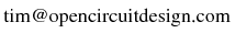
|
Last updated: October 28, 2025 at 9:51am