

cutbox [none|box|llx lly urx ury]
where llx lly urx ury are points of a rectangle in the coordinate system of magic.
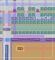
The cutbox command generates a clipping rectangle on the layout. This is used for two purposes: Limiting the amount of output to generate for a large layout, and to create vertical or orthogonal cross-sections of a layout.cutbox none removes any existing cutbox. cutbox box creates a cutbox equal to the cursor box boundary. Otherwise, cutbox is followed by two coordinate pairs representing the cutbox lower-left and upper-right corners, in magic (not CIF/GDS) units.
cutbox is implemented as a built-in wind3d window command in magic. It can only be invoked from a window created with the specialopen wind3d command, or the render procedure. Note that the wind3d window is only available when magic is compiled with the OpenGL graphics option and invoked with magic -d OGL.Note that macros of the wind3d window are hard-coded, and cannot be changed with the macro, gmacro, or imacro commands. There is no ":" macro for entering commands; to enter commands from the command-line, use the tk_path_name command. The default Tk path name of the wind3d window is ".magic3d".

| Return to command index |
Last updated: October, 2004