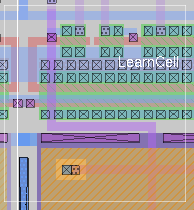


This manual describes how to generate a process design kit (PDK), herein referred to as a toolkit, targeting a specific process. The toolkit is responsible for aiding the layout designer by providing methods to generate devices according to parameterized values, so that commonly-used devices do not need to be drawn by hand, but can be drawn automatically, and satisfy design rules.Note: This page is a work in progress and subject to change without notice.
Introduction
Downloads and Installation
Toolkit Overview
Defining a Parameterized Component
File Revision Size Date sky130.tcl 1.0.446 219.9kB July 20, 2023 gf180mcu.tcl 1.0.446 142.7kB September 14, 2023 scmos_rev1.tcl 1 11.7kB December 31, 2016 scmos_rev0.tcl 0 6.7kB June 3, 2012
Note: SCMOS Revision 1 corresponds to magic version 8.1.124 and more recent versions. Revision 0 corresponds to all other versions. They are not mutually compatible. Revision 1 adds two additional required routines per device: "convert", to convert between values from a SPICE netlist and the PDK parameter names and values; and "dialog", to specify the way the dialog will be shown for the device.The sky130 and gf180mcu device generator scripts are fully developed parameterized cell setups for the SkyWater 130nm sky130 and the Global Foundries GF180MCU processes, respectively. They are not the actual file used in the installed PDK but are "template" files that are pre-processed to extract information for a specific process variant. They should be used only the context of the open_pdks installer. These two foundry processes are fully open-source, allowing the complete set of device generators to be published.
Every defined device needs to define five procedures:Usually, a PDK will have som basic routines for each component type, like "mos_draw" that handle most basic devices for the process and can be extended by passing local parameters. The parameterization is handled by passing around a Tcl dictionary variable called parameters and merging it with local modifications. The typical base dictionary for a process is called ruleset (mostly DRC rule distances). Then each device type has a dictionary that comes from the _defaults procedure, is merged with values captured from the dialog, and passed to the _draw procedure, where it is combined with a dictionary specific to the device being drawn. Most of the drawing involves manipulating the "cursor box" in magic and using a stack with the commands pushbox and popbox to save and retrieve the box in specific positions.
- device_defaults sets default parameters
- device_dialog defines the dialog GUI
- device_convert describes how to import from SPICE
- device_check checks parameter limits
- device_draw draws the device.
Last updated: October 28, 2025 at 9:38am