
Table of Contents
XCircuit Keyboard, Toolbar, and Menu Commands
XCircuit files
- The XCircuit Toolbar
- Element Construction
- Creating New Objects
- Creating and Editing Text
- Info Label Syntax for Netlists
- Element Editing
- Editing Arcs, Polygons, and Curves
- Library Creation and Editing
- Parameter Creation and Manipulation
- XCircuit Viewing Options
- XCircuit Options
- Loading and Saving Files
Tcl Extended Interpreter Reference
- Xcircuit X-Defaults
- Xcircuit configuration file (.xcircuitrc)
- Standard xcircuit library files
- Standard xcircuit font vector files
- Standard xcircuit font encoding files
- Extended xcircuit font encoding files
Python Embedded Interpreter Reference
XCircuit PostScript Reference
Comments about notation: Keyboard single-key macros for commands, if available, are listed in parentheses after the command name. Menu buttons, if available, follow in italics. The menu button is given as a list of submenu names to traverse separated by arrows ("->"); multiple choices are denoted by separating the choices by a vertical bar ("|").
The toolbar is a column full of icon buttons that is on the right-hand side of the window. Each button performs a simple function. The topmost buttons define various modes of operation in which the mouse buttons are bound to different functions. When a specific set of mouse button bindings is in effect, the corresponding tool button is highlighted with a heavy boundary, accented in green. The buttons in the middle are "tool/action" buttons. These can either act like the tool buttons described above, or as actions. An action happens when one or more elements in the drawing is selected when the toolbar button is pressed. The corresponding action happens for only those selected items, and mouse button bindings are modified only for the duration of that action. Any tool that was in effect prior to the action remains in effect after completion of the action. The buttons at the bottom are action-only buttons. They do not have corresponding mouse button bindings. They perform a single action, such as zooming in or out, popping up a window, or generating a pulldown menu. Each toolbar button is described below:
Pan tool
- This tool makes the left mouse button act as a window panner. Tapping the left mouse button grabs the window and moves it with mouse motion. The middle mouse button ends the pan, and the right mouse button cancels it and returns to the original view.
Wire tool
- This is the "traditional" XCircuit tool, and was the only set of mouse button bindings before the "tool" concept was added. The left mouse button starts a wire or adds another segment to a wire. The middle mouse button finishes the wire. The right mouse button cancels and removes the last wire segment. The escape key cancels and removes the entire wire, equivalent to pressing the right mouse button until there are no segments remaining.
Box tool
- In this tool mode, tap the left mouse button to start a box. Press either the left or middle mouse button to finish the box. The right mouse button cancels and removes the box.
Arc tool
- In this tool mode, tap the left mouse button to start a circle. Tapping the left mouse button again cycles through editing the circle diameter, start angle, end angle, and minor axis diameter. The middle mouse button finishes the circle/arc/ellipse. The right mouse button cancels the last edit operation. The escape key cancels and removes the arc, equivalent to pressing the right mouse button until no more edit operations are left to undo.
Spline tool
- In this tool mode, tap the left mouse button to start a circle. Tapping the left mouse button again cycles through editing the circle diameter, start angle, end angle, and minor axis diameter. The middle mouse button finishes the circle/arc/ellipse. The right mouse button cancels the last edit operation. The escape key cancels and removes the arc, equivalent to pressing the right mouse button until no more edit operations remain to undo.
Text tool
- In this tool mode, tap the left mouse button to start a label. Tap the left or middle mouse button to finish the label, and the right mouse button to cancel it. The type of label created is determined by the menu items Netlist-->Make Pin, Netlist-->Make Info Pin, Netlist-->Make Global Pin, and Text-->Make Label. When any of these menu options is chosen, the color of the letter "A" inside the icon changes to reflect the type of label being created: Black for normal labels, Red for pin labels, Gold for global pins, and Green for info labels.
Move tool/action
- When no elements are selected, this button acts as a tool. The left mouse button selects the nearest object and starts to move it. Pressing the left or middle button completes the move, and the right mouse button cancels it. If one or more elements is selected, this button performs a move "action". The selected elements are immediately picked up and follow the pointer until placed with another left button or middle button click.
Copy tool/action
- When no elements are selected, this button acts as a tool. The left mouse button selects the nearest object, creates a highlighted copy of it, and starts a move action. Pressing the left mouse button places the copied element, generates a new copy, and continues the move action. The middle mouse button completes the move and does not generate any more copies. The right mouse button cancels the last copy-and-move action, and the escape key cancels and removes all copies made. If one or more elements is selected when the toolbar button is pressed, this button performs a copy "action". The selected elements are immediately copied, highlighted, and follow the pointer until placed according to the button bindings described above.
Edit tool/action
- When no elements are selected, this button acts as a tool. The left mouse button selects the nearest object and starts to edit it. Pressing the left button continues the edit by moving to the next editable point, depending on whether the element is a polygon, arc, curve, path, or label. The middle mouse button accepts and completes the edit. The right mouse button cancels the last edit operation on the element, and the escape key cancels all edit operations made on the element. If a single element is selected when the toolbar button is pushed, this button performs an edit "action". The selected element is edited according to the mouse button bindings described above. Currently, there is no method for editing multiple elements at the same time.
Delete tool/action
- When no elements are selected, this button acts as a tool. The left mouse button selects the nearest object and deletes it. Pressing the middle button selects additional elements, all of which will be deleted on the next left mouse button press, and the right mouse button unselects all selected elements. If one or more elements is selected when the toolbar button is pressed, this button performs a delete "action". The selected elements are immediately deleted.
Rotate clockwise tool/action
- When no elements are selected, this button acts as a tool. The left mouse button selects the nearest object and rotates it. Pressing the middle button selects additional elements, all of which will be rotated on the next left mouse button press, and the right mouse button unselects all selected elements. All groups of elements and most single elements are rotated about the cursor position. Single object instances, labels, and arcs, however, are rotated about their own points of origin. Unlike the "r" and "o" key bindings, which are specifically bound to rotation amounts of 30 and 5 degrees, respectively, the rotate tool rotates by the amount selected from the menu Edit-->Rotate/Flip-->Rotate CW. Note that rotation by increments by amounts less than 90 degrees may cause elements to get "off grid", which can make three rotations by 30 degrees not equivalent to a single rotation by 90 degrees. To keep objects on-grid through rotations, select Edit-->Rotate/Flip-->Rotate CW 90 from the menu and use the rotate tool/action button.
Rotate counterclockwise tool/action
- This tool/action button behaves exactly like the clockwise rotate button (see above), except that rotations are in the counterclockwise direction, and rotation increment amounts are selected from the menu Edit-->Rotate/Flip-->Rotate CCW.
Flip horizontal tool/action
- When no elements are selected, this button acts as a tool. The left mouse button selects the nearest object and flips it horizontally. Pressing the middle button selects additional elements, all of which will be flipped on the next left mouse button press, and the right mouse button unselects all selected elements. Flips of multiple elements and most single elements are made across an imaginary vertical line running through the cursor x position. Single object instances, labels, and arcs are flipped across the axis of their own origin. Note in particular that if an object instance is rotated by 90 degrees, the flip may appear to be a vertical flip, since it is relative to the object's coordinate system. If one or more elements is selected when the toolbar button is pressed, this button performs a flip "action". The selected elements are immediately flipped according to the rules outlined above.
Flip vertical tool/action
- This tool/action button behaves exactly like the horizontal flip button, except that objects are flipped vertically across an imaginary horizontal line that is either through the cursor's y position or through the (single) element's origin.
Scale tool/action
- This tool/action button changes the scale of selected elements (text, object instance, and in-line graphics). When used as a tool, click on the element to get a scale outline box to modify the scale interactively. The scale box may appear to be on a coarse snap grid due to the implementation of the scale algorithm. Reduce the snap space to get better resolution of the element scale. When used as an action on a selected element, a pop-up window will be generated, prompting for the element scale. This can be used to enter specific scales for items in mechanical or otherwise strictly scaled drawings.
Push (descend) tool/action
- When no elements are selected, this button acts as a tool. The left mouse button selects the nearest object instance and descends into its object for editing. The middle mouse button will select multiple elements, but note that no more than one element can be selected when performing a "push".
Pop (return) action
- This button performs a single action, returning to the level of hierarchy above the object being edited. If the object being edited was not reached via a "push" action, then no action is performed.
Make tool/action
- When no elements are selected, this button acts as a tool. The left mouse button selects the nearest object and opens the "Make Object" dialog window. Pressing the middle button selects additional elements, all of which will be added to the new object on the next left mouse button press. The right mouse button unselects all selected elements. If one or more elements is selected when the toolbar button is pressed, this button generates the "Make Object" dialog. After completion of the dialog entry, the tool reverts back to the tool that was in effect prior to the action.
Join tool/action
- When no elements are selected, this button acts as a tool. Pressing the middle button selects elements. The left mouse button adds the nearest element (if there is one) to the set of selections, then attempts to join all of the elements into a single polygon or path. The right mouse button unselects all selected elements. If more than one element is selected when the toolbar button is pressed, this button performs a join "action". The selected elements are immediately joined, if it is possible to do so, or else an error message is generated.
Unjoin tool/action
- When no elements are selected, this button acts as a tool. The left mouse button selects the nearest path and breaks it into its separate components. Pressing the middle button selects additional paths, all of which will be disassembled on the next left mouse button press. The right mouse button unselects all selected elements. If one or more elements is selected when the toolbar button is pressed, this button performs an immediate "unjoin" action. "unjoin" has no effect on elements other than paths, and no message is generated.
Color menu
- This button brings up the following menu, which is simply a conveniently located copy of the menu at Options-->Elements-->Color:
This menu can be used to select the currently active foreground color for new elements, or to add a new color to the list.
Line/Border menu
- This button brings up the following menu, which is simply a conveniently located copy of the menu at Options-->Elements-->Border:
The border menu sets the line style for lines and polygon, spline, arc, or path borders. The "Square Endcaps" options allows control (individually, for each element) over whether XCircuit terminates line segments with rounded or square endcaps. The "Manhattan Draw" and "Manhattan Edit" options force wires and polygon line segments to stay in horizontal or vertical alignment, when creating wires or editing existing wires and polygons, respectively. The "Bounding Box" option makes the selected item (restricted to one polygon only) a bounding box, which will force the bounding area used when generating the output page (can be used to prevent the drawing from being centered on the output page, for example). The "Clipmask" option will make a selected element into a clipping mask, in which the element directly above it in the stacking order will be clipped to the boundary of the clipping element, showing only that part that intersects. Neither the clipmask or bounding box items can be selected as global options; they apply only to selected elements.
Fill menu
- This button brings up the following menu, which is simply a conveniently located copy of the menu at Options-->Elements-->Fill:
The fill menu allows filled polygons to have stippled fills, giving them a sort of fake transparency. It is generally recommended not to use the transparent stipples unless necessary, as they tend to be compute-intensive when rendering and device-dependent (depending on the output device resolution).
Parameter menu
- This button brings up the following menu, which is simply a conveniently located copy of the menu at Options-->Elements-->Parameters:
These are the numeric parameters. When they are selected for a specific element, when that element is part of a library object, that element's properties become instance-dependent. It has no obvious effect on elements on a top-level page. An example of numeric parameters can be seen on the analog elements page, where they are used to counter-rotate, reposition, and rejustify all the text in the rotated version of each component.
Parameter window
- This button brings up the following window:
This window shows each key:value pair belonging to an object instance. It tracks selected object instances, displaying the parameters of their objects and the values of each of those parameters for the specific instance. When editing a page or object, with nothing selected, the display is the parameters of the page or object itself, and the values are the default values that are independent of any instance. To change a parameter value, click on the parameter value in the "Value" column. To insert a parameter into a label, click on the parameter key in the "Key" column.
Library
- This button switches the current view to the currently active library page. If already on a library page, the button switches the view to the next library page. It is equivalent to typing the "l" key.
Library directory
- This button switches to the library directory, showing all of the library pages at once. It is equivalent to typing the "L" key.
Page directory
- This button switches to the page directory, showing all of the schematic pages at once. It is equivalent to typing the "P" key.
Zoom in
- This button zooms in on the current view. It is equivalent to typing the "Z" key
Zoom out
- This button zooms out on the current view. It is equivalent to typing the "z" key
Info window
- This button brings up the following window:
This helper window gives basic information about the active key bindings and the functions they invoke.
Creating new elements
Element creation functions which are available from the toolbar are described in the section on the toolbar, above. The tools all map the "start" function for the element to the left mouse button. However, regardless of the tool, every element can also be generated from both a menu button selection in the main menu, that sets the tool and is equivalent to pressing one of the toolbar buttons, and with a key macro that substitutes for the left mouse button, but works in any tool mode. In the list below, each element creation function name is followed by a key binding, in parentheses, and optionally by the (text) path to a menu button, in italics.There is a helper function for remembering the different button bindings for starting, completing, and canceling each element type. By clicking on the light blue button at the bottom of the window, which displays the name of the currently active toolbar tool, you will get a window that replaces the usual message window and instead displays the button bindings for each mouse button.
- Make Wire (w)
Basic operation for drawing lines and polygons, and the default toolbutton tool at startup. A ``tap'' (brief press) of Mouse button 1 fixes the endpoint of a line segment. The pointer position after subsequent pointer motion determines the other endpoint.
Mouse button 1 finishes the line segment and begins a new one.
Mouse button 2 completes the line segment and ends the command.
Mouse button 3 deletes the last line segment and returns the cursor to the endpoint position of the previous line segment, or cancels the command if there are no line segments left to edit.
- Make Box (b) Edit->Make Box
Convenience function for closed, rectangular polygons. The position of the cursor when the key or mouse button is pressed marks one corner of the box. The pointer position during subsequent pointer motion defines the diagonally opposite corner.
Mouse button 2 completes the arc and ends the command.
Mouse button 3 cancels the command.
- Make Arc (a) Edit->Make Arc
Create a circle or ellipse. The position of the cursor when the key or mouse button is pressed marks the center of the arc or ellipse. Subsequent pointer motion defines the radius.
Mouse button 2 completes the arc and ends the command.
Mouse button 1 switches between radius, endpoint, and ellipse minor axis editing.
Mouse button 3 cancels the command.
- Make Spline (s) Edit->Make Spline
Create a curve. The position of the cursor when the key or mouse button is pressed marks one endpoint of the curve. The pointer position during subsequent pointer motion defines the other endpoint. The control points are initially fixed.
Mouse button 2 completes the curve and ends the command.
Mouse button 1 switches between endpoint and control point editing.
Mouse button 3 cancels the command.
Note: In XCircuit version 3.7.24, a new method was added: If you select a polygon (wire) and then select "Make Spline", the polygon will be converted into a smooth curve approximation.
Note: The Bézier curve generating algorithm uses the parametric form described in the Adobe PostScript Language Reference Manual. It is not a spline, though I have abused the terminology because it makes the "s" macro easier to remember. "c" stands for "copy", not "curve"!
- Make Text (t) Text->Make Label
See ``Creating and Editing Text'', below. The menu button configures the toolbar "text" tool to create normal labels. Use the equivalent menubuttons in the "Netlist" menu to configure the tool for pin labels and other labels meaningful to the schematic capture netlister.- Make User Object (m) Edit->Make User Object
This is a powerful feature of Xcircuit. This command creates new objects which act just like built-in library objects. An instance of the object is kept on the User Library page, where it can be grabbed whenever a new instance is required.
All elements which are currently selected when the command is executed by key or button press will be compiled into a new user object. The individual elements will be replaced by the new object. The user is prompted for a name for the new object.
The Cancel button on the popup window cancels the command.
The Okay buton on the popup window completes the command.
Note: For efficiency in the PostScript output, it is recommended that an object be created for any part of a drawing which is used more than once. However, any single object should not have more than about a hundred components, or it may exceed the capabilities of the PostScript rendering device. The PostScript internal limit is device-dependent and cannot be known a priori. Xcircuit will flag a warning if an object contains an unusually large number of components, but the condition is not treated as an error.- Make Path (join elements) (j) Edit->Join
Paths are another powerful feature of Xcircuit. A path is a linked set of line segments, curves, and arc segments which is treated as a single unit. The unit can be colored, stippled, filled, and bordered like a single polygon, arc, or curve.
All elements (may only be polygons, arcs, and curves) which are currently selected when the command is executed by key or button press will be compiled into a single path, provided that a single path can be found. If the path has more than two free endpoints, then a single path cannot be constructed and the command will fail. Note that arcs will be converted to (nearly) equivalent curves when the path is created.
The Make Path command cannot be canceled but can be undone using the ``unjoin'' command (see below). Note that arcs that are converted to curves will not be converted back to arcs on execution of "unjoin".
Path points can be edited directly with the ``edit'' command, like polygons or splines, except that where points are common to two elements in the path, both elements will track. In XCircuit version 3.7 and higher, adjoining curves have tracking control points when the option "Link Curve Tangents" is selected. Otherwise, tangents for each curve can be adjusted separately.
Note: In some pathological cases, a potential path which crosses itself too many times may have a perfectly good solution which xcircuit cannot find, and so cannot execute the "join" command. If this occurs, xcircuit will report "too many free endpoints", and the path will have to be divided into two or more subpaths.- Import Graphic Image File->Import->Import Graphic Image
See "Loading and Saving Files" below. Creates an element of the type "graphic", which is a graphic images, by loading it from a fil. Most graphics are imported from files. However, the Tcl/Tk command line allows the option "graphic make gradient" to generate in-line linear gradient fields.Creating and Editing text
- Make Text (t) Text->Make Label
Begins a text label. The text is always horizontal and left- and bottom-justified initially. A vertical green bar marks the current position in the text. The <RETURN> key finishes the label and ends the command. Text may be altered during entry using menu commands, control characters, and keypad macros (see below).
Mouse buttons 1 and 2 complete the text, equivalent to typing <RETURN>.
Mouse button 3 cancels the command.
- Make Pin Label (T) Netlist->Make Pin
Begins a ``pin'' label. A pin label is like a normal label for normal functions such as move, copy, edit, etc. However, it has special meaning to the schematic capture system and has several distinguishing features:
- Defaults to red color, although this can be overridden.
- Has a position offset, so that the label's reference point can be placed on a network (the label then names the network) but keeps the label an aesthetically pleasing distance away.
- Only appears on a top-level page. That way, if the pin describes the pin names for an object, they won't clutter the schematic page where that object is used. If the object is edited (with the ``push'' command), then the object becomes the top-level page and the pin labels are shown.
- Shows its reference point as an "x" on the xcircuit page. The "x" does not appear in the PostScript output, one of the only cases in which the xcircuit display differs from the printed page.
- Names networks: for purposes of creating netlists, if a pin's reference point is placed on top of a wire or symbol I/O point, that label then becomes the name of the associated electrical network.
- Is duplicated between schematic and symbol. The main purpose of pins is to connect networks from a circuit element's symbol to its schematic; implied is a 1:1 correspondence between pins on the symbol and pins in its schematic.
- Can be one of three types:
- Local: A ``normal'' pin which indicates the correspondence of I/O between a symbol and its schematic.
- Global: A pin which indicates the same network regardless of the position in the schematic hierarchy. Used, for example, for power and ground networks.
- Informational: A ``pin'' of sorts which does not name a network, but instead provides information to the netlist generator about a circuit symbol. A ``sim'' or ``spice'' info label tells xcircuit how to write the device to the netlist output file. A ``pcb'' info label tells xcircuit how to name the device in the output file (see the section Info Labels for more detailed information).
- Changing text color Elements->Color->(color)
During text edit modes, selecting a color from the color menu will change the text color beginning at the edit point.- Changing text scale Text->Text Size
During text edit modes, selecting text size will scale the text beginning at the edit point. Size is a (floating-point) scale factor relative to the default (starting) size of the label.- Changing Font Text->Font->Times Roman | Helvetica | ...
Font families can only be changed from the menu, since the keyboard is not available for key macros during text entry. Note that font family and style are orthogonal properties: to go from (say) Times Bold to Helvetica Italic will require both a font and a style change.
Fonts are encoded for the predefined fonts (Times Roman, Helvetical, Courier, and Symbol). Other fonts may be added with appropriate .lps and .xfe files, preferably in the fonts subdirectory of the xcircuit lib path.- Changing Font Style Text->Style->Normal | Italic | ...
Font style changes act the same way as font changes. Font style change does not change the font family (see above). Choices are Normal, Italic, Bold, and Bold-Italic.
Note: Style changes apply only to the standard fonts (Times, Helvetica, Courier). Bold and Bold-Italic styles are not available for the Symbol font: this is an unfortunate limitation of the "standard 35 fonts" used by most PostScript printers.- Changing Font Encoding Text->Encoding->Standard | ISO-Latin1 | ...
Font encoding changes act like font style and family changes. Standard (Adobe) Encoding and ISO-Latin1 Encoding are included, as they are part of the PostScript spec. ISO-Latin2 (Eastern European) and ISO-Latin5 (Turkish) encodings are also available but currently require postprocessing the xcircuit output file with a separate program called ogonkify to generate correct output on a PostScript printer. See file README.ISOLatin2 in the source distribution for details.- Character Insertion Text->Insert->Backspace | Halfspace | Quarterspace | Character | Return
Allows insertion of special text features, including backspace, half space, quarter space, return, and a special mode for input of any character in the 256-value font encoding (see "Text Special Characters" below).- Changing Justification (Keypad numbers) Text->Justification->Left Justified | Center Justified | ...
Changes the position of the text relative to its origin. The origin of the text is marked during editing mode with a small "x". With left-justified text, the "x" is to the left of the text; similarly for other justifications. The menu buttons can only select vertical or horizontal alignment at one time. The keypad macros can adjust both vertical and horizontal alignment at the same time. The position of the key relative to the center of the keypad matches the position of the text relative to the origin. Thus, for instance, keypad "9" makes left- and button-justified text, and keypad "5" makes centered text.
Note: Some systems will require that the keypad number be typed; other systems require typing shift-keypad number. This behavior is dependent on the X-server, xmodmap settings, and Num Lock setting.
Note: it is strongly recommended to justify text appropriately for the position of each label relative to its surroundings. This overcomes problems which may arise due to device-dependent differences in character widths and spacing which may occur between different rendering devices.- LaTeX-mode Labels Text->LaTeX Mode
When a label is set to "LaTeX mode", it is assumed by XCircuit that the contents of the label are meaningful to the LaTeX compiler. When a label is so specified, XCircuit handles the label differently in two ways:Every time the XCircuit file is changed and re-written, the accompanying .tex file will also be re-written.
- The text of the label is not visible in the output. This is because neither XCircuit nor the PostScript interpreter know how to compile and format the text.
- When the file is written, an accompanying file with the extension .tex (with the same root name) is created along with it. The .tex file contains a flattened list of all the labels in the xcircuit file, translated into LaTeX format. It also contains a call to includegraphics (previously epsfig) to read in the xcircuit file. This .tex file can be read directly into a LaTeX document with the command:
\input{filename.tex}The method used for including the file was changed in XCircuit version 3.6.133 (June 2008) by implementing a solution provided by Alex Tercete. With this method, the LaTeX output will scale with the "output scale" in XCircuit, and any additional scaling within the LaTeX document. The output will be centered on the page.
The following restrictions apply only to XCircuit versions prior to 3.6.133:
Note: Because the backslash character is common in LaTeX files, and because only ASCII characters are generally used in LaTeX, the usual behavior of the backslash key to switch to the special characters window is suspended when the label is in LaTeX mode. The character map can still be reached from the XCircuit menu.
- The graphics appear in the LaTeX document exactly as scaled in XCircuit. It cannot be resized from within the LaTeX document; resizing must be done by changing the scale in XCircuit.
- Size of all text is controlled from LaTeX, not from XCircuit. The scale of all text labels will be the same as all surrounding text, and can be changed with the usual LaTeX font sizing commands prior to the \input command.
- Because the XCircuit .tex output uses the epsfig command, it is necessary for the LaTeX document to include the epsfig package in its setup section.
- Over- and Underlining Text->Style->Underline | Overline Overlines and underlines are selected from the menu like font and style changes. These stay in effect until the next font or style change, sub- or superscript, or a "no line" escape sequence.
- Sub- and Superscripts (Keypad -/+) Text->Style->Subscript | Superscript
Subscripts and superscripts operate like under- and overlines, except that they can be nested, and remain in effect through font and style changes. An embedded ``normalscript'' escape sequence returns to the original script size and alignment (not just the previous one).- Returning to ``normal'' script (Keypad Enter) Text->Style->No Line | Normalscript
These embedded commands cancel overlining and underlining, or subscripts and superscripts.- Text character kerning Text->Insert->Kern)
Allows kerning (positional shift relative to "normal" position) of substrings. A popup window requests the X,Y offsets (in integer units relative to the text size). Kerning is additive, so returning to the original character position requires a second kern command with values -X, -Y.- Text selection
Text can be selected in several ways. A first-mouse-button grab or a second-mouse-button tap always selects the whole label. A select-box selection (hold second mouse button and drag) can be used to select a portion of a label. Only the selected portion will be highlighted. Editing (see below) a text portion causes that portion to be bounded by vertical green bars. Subsequently, the "Delete" key will erase the entire selection (block delete). Substring selection is critical for the use of the ``Parameterize'' function for creating and placing string parameters.- Text editing (e) Edit->Edit
The cursor is placed at the nearest string position for text editing. Text editing is just like text entry. Arrow keys may be used to move the cursor around inside the text string, and the HOME and END keys may be used to move instantly to the beginning or end of the string. Mouse buttons 1 and 2 or key <RETRUN> complete the command.
Mouse button 3 cancels the command and reverts back to the previous text string.
Note: Text always begins with a font specifier. The cursor position cannot be moved in front of the font specifier, and the initial font specifer may not be deleted, although it can be changed. Note: The order of escape sequences embedded in the text is important for the appearance of the text. Keep this in mind if attempting to alter escape sequences manually in the PostScript output files. Escape sequences cannot be directly seen in a text string, but show in the message window at the bottom of the program window.- Substring parameterization
When an object that is not a top-level page is in the xcircuit window, substrings may be parameterized. This means that the substring becomes a "parameter" of the object. Each instance of the object may then take the default parameter or define its own value (alternate substring). This method highlights the difference between objects and their instances. When an object is edited by "pushing" the object from the library page, altering a parameterized substring alters the default value. When an object is edited by "pushing" the object from a non-library page, alterning a parameterized substring alters the instanced value. The schematic capture tutorial contains more information on this method.Parameterization appears as the string command "Start Parameter" and "End Parameter" printed in the message window during label edits. Otherwise, parameterization is invisible except for the effect of changing a parameter instance.
- Text special characters
All characters from the 256-character encoding vector of each PostScript printer font may be included in text strings. This is more characters than are (usually) available from a single keyboard. Several methods exist for entering special font characters. The first is to type a backslash (\) character during text entry (equivalently, select Text->Insert->Character from the menu), which brings up a page containing the 256-character array. Simply click on the character you want.
Alternately, a keyboard can be set up using xmodmap for special character entry through the use of keyboard modifiers. Xcircuit will handle the use of Alt- and Meta- key combinations properly, although it is unable to handle Multi-Key (Compose) sequences.
Prior to version xcircuit-2.0a10, special character entry was enabled through the use of backslash escape sequences. That cumbersome interface is obsolete, but for purposes of support, the espace sequences are listed on the page of special characters. Warning: many small inline images of characters may cause lengthy download time.- Text ``Alt-'' functions
Several ``Alt-'' key combinations are meaningful in text edit mode, and can be used for quick access to functions otherwise available only through cumbersome menu selections.
- Alt-f Toggle font (runs through the list of available fonts)
- Alt-b Bold font
- Alt-i Italic font
- Alt-n Normal (non-bold, non-italic) font
- Alt-e Change font encoding
- Alt-o Overline
- Alt-u Underline
- Alt-Enter Insert "return" (newline) character
- Alt-p (Deprecated) Insert a parameter: If only one parameter exists for the object, it will be inserted automatically. If more than one parameter exists, the user will be prompted to choose which one to insert. The Tcl-based version of XCircuit replaces this function with the parameter pop-up window (toolbar button
Info labels tell XCircuit how to generate a netlist. They exist inside symbols or schematics. When XCircuit traverses the schematic hierarchy and finds a symbol containing an info label, it parses the info label, and dumps the result to the netlist file (or a structure, in the case of PCB netlists, which is in turn parsed to create the netlist). When XCircuit finds a schematic containing an info label, it parses the info label, and dumps the result along with the netlist information. The position of parsed info labels relative to the netlist information can be controlled.Each info label is of the form:
net_type[prefix][index]:contentThe net_type can be "spice", "sim", or "pcb". The index is optional. If not specified, then lines with the same net_type will be parsed and dumped to the netlist in the order they are encountered. To ensure a specific order, each line can be indexed with a number giving its relative order. In addition, the number may be preceded by a prefix, which may be one of the characters "@" or "-". Info labels with the prefix "@" are parsed prior to any netlist output for the subcircuit, including the subcircuit call. It is appropriate to use, for example, for include files that contain device subcircuit definitions for a specific process. Info labels with the prefix "-" are parsed within the subcircuit definition but after all netlist information has been written. If no prefix is given, then the line is parsed within the subcircuit definition but before any netlist information has been written.The content text may contain any plain text in the XCircuit label format, including embedded parameters and other escapes. Parameters are substituted with their appropriate value when parsing the line. Most other text escapes are ignored, except for the following exceptions:
Naturally, the primary actions needed to be performed when parsing an info label are:
- overline
- Overlines are converted to a "!" character, which is a widely-accepted character meaning "logical NOT".
- font
- Most font changes are ignored. However, the symbol font character Greek "mu" as well as the ISO-Latin1 character "mu" are both checked and converted to "u" in the netlist output.
Component parameters are either plain text if they don't change on a per-instance bases, or XCircuit parameters, if they are. Parameters can be inserted into the text by clicking on the appropriate parameter key in the parameters window (
- determining the component index
- determining the nets connected to component pins
- generating parameters of the component
The component index should be specified using the special parameter name "index" with the special default value "?". XCircuit uses this information to automatically generate component index values. XCircuit uses base-36 encoding to handle component indexes. Base-36 encoding allows both alphabet characters and numbers, which is appropiate for legal SPICE names following a device type. When auto-numbering components, only decimal base numbers will be used. However, the base-36 parsing means that an index can be forcibly set to a non-numeric value (like "test1") without disturbing XCircuit's automatic generation of numeric component indices. Finally, there is a special syntax to lines for which the net_type is "pcb". Due to the special nature of the PCB netlist syntax, which ennumerates nets one at a time, and lists the component connections of each, XCircuit uses the info label line to determine the component name. PCB format lines use the syntax:
- %ppin_name
- Write the name of the network connected to pin pin_name to the output. The pin_name is normally the (ASCII text) name of the pin, but if the pin name is a parameterized string, it can also be given as the parameter value. If pin_name contains spaces, it should be put in quotes. There is no space between the "%p" and the pin name.
- %i (deprecated)
- Write the component index. There is no way to specify a component index using this method, which is why it is preferred to use a parameter to indicate the component index.
- %n
- Write the name of the symbol, without any technology prefix
- %N
- Write the fully-qualified name of the symbol, including the technology prefix.
- %x
- Write the X position of the symbol in the schematic.
- %y
- Write the Y position of the symbol in the schematic.
- %Ffilename
- Dump the contents of the file filename to the netlist output. Remember the name of the file. If the file is requested more than once, the requests are ignored.
- %ffilename
- Dump the contents of the file filename to the netlist output. The contents will be written every single time the line is encountered (thus, if the intention is to include SPICE model statements, for example, the %F escape is the correct one to use).
- %vkey (deprecated)
- Write the value of the parameter whose key is key. Normally, one would simply embed the parameter directly rather than include it by reference with the "%v" escape.
- %r
- Write a carriage return to the output. Note that an embedded carriage return (key Alt-Return) is also written to the output as a carriage return.
- %t
- Write a tab to the output. This is a standard ASCII tab character, and not to be confused with embedded tabs in XCircuit labels, which cannot be directly translated into ASCII.
- %%
- Write the ASCII character '%' to the output.
pcb[prefix][index]:{class}{index} [pin=net] ...The "{class}" is some fixed class name like "C" for capacitors or "U" for integrated circuit chips. The "{index}" is the component index (as described above). Then optionally, there may be a space followed by pairs of pin names and net names. These are used to tell XCircuit what to do with pins that do not show up in the symbol. In the non-PCB info label types, a pin that does not appear in the symbol can simply be added to the info label as plain text. Since PCB netlists traverse the structure looking for pins, pins that are not explicitly drawn on the symbol must be recognized some other way. Normally, one would use this method to indicate connections of global pins like power and ground that one may not want to draw directly on the symbol in the schematic, to avoid unnecessary clutter. See the "quadparts" library in the XCircuit distribution for an example of this syntax.
Unless otherwise stated, all of the commands below have the following behavior which depends on the way they are called:
Menu button/Toolbar button: The toolbar button, as described above, sets XCircuit into a specific mode in which the mouse buttons are bound to actions that related to the tool function. The menu button of the same name as the tool simply invokes the toolbar button. For toolbar buttons of the type "tool/action" (see description of toolbar buttons above), if elements are already selected when the button is pushed, or the menu button is selected, they will also be acted upon immediately by the function. The mouse right button will generally cancel the function, although similar but distinct functions are performed by the right mouse button, the escape key, and the "undo" command ("u" key).
Keyboard macro: If an element or elements are already selected, the macro will act upon them. Otherwise, the program will look for any elements close to or underneath the cursor, select them, and perform the function upon them. If no appropriate element is found near the cursor, then the command is ignored.
- Delete (d) Edit->Delete
Deletes elements. Note that when object instances are deleted, it is the specific instance of the object, not the object itself, which is removed (see the library Delete function below).- Undo (u) Edit->Undo
XCircuit has an (almost) comprehensive "undo" mechanism that will allow sequences of functions to be undone.- Redo (U) Edit->Redo
The comprehensive "undo" mechanism can read the event stack both backwards and forwards, allowing functions that have been undone to be redone.- Copy (c) Edit->Copy
Used to make a copy or copies of elements. After the command is chosen, a copy of all the selected elements is made and may be dragged around the screen to the desired position using the pointer.
Mouse button 1 places the current copy at the position of the pointer, then immediatly creates a new copy and continues the copy function.
Mouse button 2 places the current copy at the position of the pointer and completes the command.
Mouse button 3 removes the current copy and ends the command. Previous copies which have been made are not affected.- Deselect (x) Edit->Deselect
Removes items from the group of selected elements. Un-selection differs from selection in that the selection mechanism selects only one element at a time. In deselection, all elements which qualify as being near the cursor are deselected. The menu function, not having a reference point, deselects everything that is selected. Note that after selecting elements, the "undo" command will unselect each element in turn (it "undoes" the selection command), and the right mouse button and/or the escape key will deselect everything.- Rotate CW 15 degrees (r)
Rotation is self-explanatory, but the exact behavior depends on the elements chosen to be rotated: Object instances are rotated around the object's center point, defined by the (0,0) position (origin) in the coordinate system of the object. Text is rotated around the text's origin as defined by the text justification. Arcs are rotated about their center, meaning that the angles of the endpoints are rotated. This is true for ellipses, too: ellipses are only defined with the major and minor axis perpendicular to the drawing window axes. However, entire ellipses can be rotated by using "Make User Object" (see above) to turn the ellipse into an object, and then rotating the object instance. Splines, polygons, and paths are rotated around the reference point of the cursor. Note that due to roundoff errors, this can cause distortion in the element and is not recommended. Rotation which exactly preserves relative point coordinates is better effected by making an object out of the polygon (or curve, or path), and then rotating the object instance, as described above for ellipses. When more than one element of any type is selected, the group is rotated around the reference point defined by the cursor position.
Elements may be rotated while they are being held and dragged around the window. When rotated while held, elements remain selected, which makes this method a convenient way to rotate elements (especially text).- Rotate CCW 15 degrees (R)
Counter-clockwise rotation. Behavior the same as above.- Rotate CW 5 degrees (o)
More finely-spaced clockwise rotation.- Rotate CCW 5 degrees (O)
Finely-spaced counterclockwise rotation.- Flip Horizontal (f)
Like rotation, flipping behavior depends upon the type of element being flipped: Object instances are flipped around the object's point of origin, and flipping is relative to the object's own Y-axis, not (necessarily) the axis of the drawing window. Arcs, curves, polygons, and paths are all flipped around the Y-axis defined by the X-position of the pointer. Text cannot be flipped, although flipping will reverse the justification. If backwards text is desired for some reason, it can be made by creating an object ("Make User Object") out of the text, clearing the "Flip Invariance" option for that text, and then flipping the object instance. By default, all text is set "flip invariant" and remains in correct orientation through flips of both the text and object instances containing the text.- Flip Vertical (F)
Vertical flipping acts exactly like horizontal flipping except that flipping occurs across the X-axis.- Attach to point (A)
The "attach" function allows wires to be attached to specific points. There are several distinct uses for this, depending on the type of element that is closest to the wire endpoint when the "A" key is typed. The primary use is to constrain a line to be attached to a pin on a component symbol (object instance) in a schematic. If a wire, curve, or arc is selected, the wire will be constrained to connect to it, although the position can be moved to any part of the connected element. Object instances can also be attached to wires with the "A" key, for example, to attach an arrowhead to a line or curve. Finally, the "A" key can be used in normal mode (with nothing edited or selected) to create a wire whose initial point is attached according to the above rules. Other than the initial point attachment, this use of the "A" key is exactly like creating a wire with the "w" key (see above).- Snap to grid (S)
Causes the selected elements to be aligned to the snap-to grid. Object instance and label origins will be moved to the closest snap-to point, as will arc centers and radii, spline endpoints and control points, and all points of polygons.- Exchange order (X)
If two objects are selected, their stacking order is exchanged. The "stacking order" is the order in which objects are drawn, so it affects the appearance of which objects appear to be "on top of" or "underneath" other objects. If only one object is selected, it is brought to the "top" of the stack, unless it is already on the top of the stack, in which case it is sent to the bottom.- Raise order (])
All selected items are moved up (on top) by one position in the stacking order. Any of the selected items that are already at the top of the stacking order will not be moved.- Lower order ([)
All selected items are moved down (underneath) by one position in the stacking order. Any of the selected items that are already at the bottom of the stacking order will not be moved.- Dashed/Dotted/Solid Border (|,:,_) Options->Elements->Border->Solid | Dashed | Dotted
Changes border style for arcs, polygons, curves, and paths. The menu also has a style choice of "Unbordered". Note that it is not allowed to make an object both unfilled and unbordered, as this would render the object invisible.- Disassemble Path (un-join) (J)
This command disassembles all selected paths, and returns all polygons, arc segments, and curves to the state of separate, individual elements.- Push into object (edit) (>) Edit->Push Selected
This is the proper way to edit an object. Xcircuit is hierarchical, and objects can be nested. After a push, the selected object becomes the top level page. There is no difference between pushing into an object from any page or the library containing the object, unless the object has a parameterized string. If so, pushing into the object from the library substitutes the parameter's default value, and editing the string alters that default value. Pushing into the object from a page substitutes the value specific to that object instance. Subsequently, editing the string alters the object instance's value, not the default.- Pop out of object (<) Edit->Pop hierarchy Returns to the originating page from which a push command was executed.
- Transferring elements between pages Any element can be moved between pages. This requires an active ``grab,'' in which the element(s) is (are) selected, then grabbed; while holding down the mouse button, type a new page number (keys 1 through 9 and 0 for Page 10). The elements will be deleted from the originating page and moved to the target page.
- Change object size Options->Elements->Object Size Allows an object instance to be scaled. The scaling affects linewidths inside the object, so use of object scaling is not recommended for circuit elements (due to potential mismatch of wire lines) unless the linewidths of the object are inversely scaled to match.
- Change object color Options->Elements->Color->(color) Selected elements will take on the chosen color. The special color entry ``Inherit Color'' lets the element take its color from its parent object instance. Color inheritance is meaningful only for object instances; elements on top-level pages always inherit the color black. So, attempting to set the color of an object instance only works on those elements of the object which inherit their color.
- Edit (e) Edit->Edit Edit mode is dependent on the type of element selected. See below.
Editing arcs, polygons, and curves
- Polygon The edit warps the cursor to the closest polygon point. The point can then be moved independently of the rest of the polygon but depending on the policy set by the Options->Elements->Polygon Edit selection. With ``Normal'' edit, only the point being edited is moved. With ``Manhattan'' edit, the two nearest neighbors to the point in question are also moved to maintain manhattan geometry (i.e., both lines are either vertical or horizontal). From edit mode, mouse buttons function as follows:
From Xcircuit version 3.7, if an area selection is used to select some portion of a polygon, the whole polygon will be shown as selected, but upon start of an edit, those points within the select area will be edited together.
- Cycles between the points of the polygon.
- Ends the edit.
- Undoes the last edit action and returns to the previously edited point. If the current point was the first to be edited, then the edit command ends.
In addition to the mouse-based functions, there are several keyboard functions which operate as follows:
- i Insert a new point into the polygon. The initial point position will be on top of the current edit point, but subsequent cursor movement will reveal the new point.
- d Delete the point from the polygon. This works as long as there are more than two points (one line) in the polygon; otherwise, nothing happens.
- x Breaks the polygon into two parts at the edit point. The edit session will continue with one of the two resulting polygons (this function removed from xcircuit 3.6 and later due to technical reasons).
- A Sometimes it is desirable to have a line terminate at a particular point along another line, arc, or curve, rather than on a specific grid point. To do this, place the edit point over another polygon, arc, or curve, and type ``A''. The point will then be constrained to terminate on the selected element. Typing ``A'' a second time will release the attachment constraint.
- Arc The edit warps the cursor to the nearest arc endpoint (it has two, even if the arc is a closed circle). The arc can then be altered according to the edit cycle, as defined below.
- Cycles between the radius length, first arc endpoint, second arc endpoint, and ellipse minor axis. The center point can only be changed by moving the whole arc, not from the edit mode.
- Ends the edit.
- Undoes the last edit action and returns to the previously edited point. If the current point was the first to be edited, then the edit command ends.
- Curve The edit warps the cursor to the nearest curve endpoint. The curve can then be altered according to the edit cycle, as defined below.
- Cycles between the two Bézier curve endpoints and the two control points.
- Ends the edit.
- Undoes the last edit action and returns to the previously edited point. If the current point was the first to be edited, then the edit command ends.
- Path The edit command warps the cursor to the nearest point of the nearest path object, where edit continues as described above for the element type found (polygon, arc, or curve). Path components cannot be added or deleted; that can only be accomplished by disassociating the path components using the ``un-join'' command (``J'' macro).
Caveats: From XCircuit 3.6.56, creation of paths converts arcs into spline approximations. This makes it easier to adjust the shape of the path when editing neighboring components, as well as allowing a path to be rotated. From the same version of XCircuit, editing switches smoothly between the different path components, and points common to two neighboring components remain connected (i.e., the edit point is common to both components and changes to the point track in both components).
From XCircuit version 3.7, if an area selection is used to select some portion of a path, the whole path will be shown as selected, but upon start of an edit, those points within the select area will be edited together. This is a convenient method for stretching part of a path.
Also introduced in XCircuit version 3.7: When multiple curves exist in a path, their control points will track opposite to one another. This ensures that both curves leave the endpoint with opposite tangents, keeping the join between the two curves smooth. This behavior can be controlled by selecting "Link Curve Tangents" from the Options->Elements menu.
- Change element fill style Options->Elements->Fill->(fill type) Fill style results in ``transparent'' (stippled) fill patterns. In general, this is not recommended, as the PostScript output becomes device-dependent, and output rendering becomes much slower. However, it is the only way to get transparent effects in PostScript.
- Make element opaque/transparent Options->Elements->Fill->Opaque With the above fill styles, ``opaque'' gives a solid white background to the stipple, eliminating the transparency effect. This is not a useful function except in rare cases.
- Change element color Options->Elements->Color->(color) Color is changed to the selected color. One special entry is called ``Inherit Color'', which causes the element in question to inherit its color from the level above in the drawing hierarchy. This allows an entire object to be set to a given color. Interesting effects can be generated using combinations of inherited and fixed colors inside an object. Top-level elements inherit their color from the top-level page, which is always defined as black.
- Make element a clipmask Options->Elements->Border->Clipmask (Introduced in XCircuit version 3.7). When this menu item is chosen while a single path, arc, polygon, or curve is selected, then that element becomes a "clip mask". Any single element that is directly above this clipping element in the stacking order (the order in which elements are drawn) will only be visible where it intersects the clip mask. Normally, a clipmask path is shown with a light blue boundary. To make the clipmask path boundary invisible (as it will appear on the output page view), uncheck menu item Options->Show Clipmask Outlines.
An explanation of the difference between library pages, library files, and technologies
A fairly obvious source of confusion in XCircuit is the definition of libraries. It is important to understand the difference between library pages, library files, and technologies. These are defined as follows:
- Library page
- When XCircuit starts up, and you type "L", what you see is the set of library pages that have been loaded. XCircuit may have many library objects, and placing them in groups on pages is a good way to organize them and make specific objects easier to find.
- Technology
- Each library object has a name that is a concatenation of a technology prefix, a double colon ("::"), and the object name. The whole form, known as the "fully qualified name", must be unique, but objects in different technologies may have the same name. The prefix tells XCircuit which library file the object came from, even if the file has been split up among different pages, or if a page contains objects from more than one library file.
- Library file
- Objects are defined in library files, with the .lps extension (for "library postscript"; in other words, a postscript file containing only definitions, which will be acceptable as input to any postscript interpreter, but which will not produce any display or printout). Each library file defines, at the top, a technology name. It is legal for the file to contain objects from other technologies only if those objects are used by (contained in) objects belonging to the technology defined by the library file.
XCircuit saves library files by collecting together all objects belonging to a single technology, plus any dependent objects from other technologies, and writing them all to a single file. This is what happens when the menu option File-->Save Technology is selected. It is possible, but not wise, to have two library files with the same technology name but containing different sets of objects. It can be done for read-only files, but XCircuit will not be able to tell which object came from which library file, and so will not be able to write back the files as they were originally composed.
The Library Manager
The library manager is the best way to handle loading different technology files (or portions thereof), when adding new components or library pages needs to be done "on the fly". If libraries need to be loaded every time XCircuit starts up (such as for a project), this should be done by placing the appropriate command-line commands in the startup file.The library manager is divided into two halves. The left half concerns technology files, and the right half concerns library pages. The list "Search Directories" shows all of the directories that XCircuit will search when looking for available technology (.lps) files. By default, this list includes the installation directory where technology files included with the distribution are placed, and the current working directory. More directories can be added to this list either by clicking on the "Add Directory" button, or by changing the search path using the "config search" command (note that changes to the search directory list using config search are not immediately reflected in the library manager).
Clicking on the box below the title "Source Technology File" produces a list of all library files found in the search path. If you select one of these, a list of objects defined in that library will appear in the object list on the right side of the library manager. By default, only objects that have not yet been loaded into XCircuit are shown. If you want to see all objects, including those that have already been loaded, check the "Show Loaded" box on the bottom right corner of the library manager window.
Choose the target library page where new objects should go by clicking on the box below the title "Target Library Page". If you want objects to be put on a new page, then you should first select the button "Add New Library Page", and enter a name for the new library page at the prompt.
After all the unloaded objects in the library are shown, you have the option of selecting specific objects you need from the library, or load everything at once. You can select single or multiple items in the list. Click with the left mouse button to select single items, Shift+left mouse button to select a connected range of items, or Control+left mouse button to select any number of unconnected items. The "Load Selected" button then loads these objects onto the chosen target library page. Each library contains a dependency list, so if a selected object is imported that contains an instance of another object that is not selected, that object will also be loaded. The "Load All" button simply executes the "library load" command with the appropriate options for the chosen technology file and target library page. All objects are loaded regardless of whether or not they are selected in the library manager list.
Note that selecting all objects and pressing "Load Selected" differs from pressing "Load All" in that the former loads objects in the order that they are displayed in the "Objects" list (which is arranged alphabetically), whereas the latter loads objects in the order they appear in the technology file.
Library Manipulation Commandline Commands
- Edit Object Name (E, e)
This is the only way to change the name of an object (apart from altering the PostScript file). Acts very much like the edit (``e'') command for labels, except that special characters and functions are disallowed, because the object name must follow the same rules of syntax as a PostScript name. Disallowed normal characters (such as whitespace) will be replace by underscores. If the object's name is the same as any other object, it will be altered to make it unique by appending an underscore.- Move Object (M)
This command allows objects in the library to be rearranged. Because clicking on an object returns the user to the originating page, objects cannot be moved around like they are on a regular page. However, the method is similar. If you type "M" while the cursor is on top of an object in the library, the instance will disappear from the library page and follow the cursor around until placed or canceled. When placed, the library is re-composed to fit the object in the spot where it was placed, shifting other library objects around as necessary. Objects can even be moved between library pages by typing "l" (or selecting the library page from the menu) during a library move operation.This command also works on the "Page Directory" page in the same way, allowing pages to be rearranged. This determines the order of output in multiple-page files. No such method exists for the "Library Directory" page.
- Delete Object (D)
Unlike deletion from a page, which deletes an object instance, deletion from the library deletes the object itself. This is a non-recoverable function: all memory allocated to the object is freed. Deletion is disallowed if the object has an instance on any page in xcircuit.- Hide Object (H)
Sometimes objects are best constructed in parts, where its parts may also be objects. It is not always desirable to have these sub-parts to show up as library objects, because they are not useful to the end-user by themselves. In such cases, the object may be declared ``hidden'', and does not appear in the library. Object hiding is disallowed if the object is not a sub-part of any library object, because the object would become inaccessible.- Copy Object (C)
Object copy is different from copying object instances for the same reason that object deletion is different from object instance deletion. When an object is copied, a new object is created on the ``User Library'' page (or on the current library page), which is a separate but duplicate version of the original. An underscore is prepended to the object name to maintain a distinction between the two (but it can be altered afterward with the ``E'' edit command, above).- Create Virtual Object (V)
From version 2.5.2, xcircuit allows multiple instances of a single object to appear on a library page, provided that the object has parameters. The idea is that this works as a convenience function for inserting specific parameters into an object. For instance, it can be used to pre-assign pin numbers to different gates on a multiple-gate chip such as a 7400 quad NAND. Note that parameterized pin names only generate correct netlist output from xcircuit version 2.5.2.Parameter Creation and Manipulation
General-purpose parameter types known to XCircuit:Specific-purpose parameter types known to XCircuit (in the below, "n" may be absent, or may any integer 2 or higher):
- substring
- The substring parameter is a text label just like other text labels in XCircuit, except that it does not require the initial font designation that normal labels do. It can be embedded inside a text label, or used alone. When used alone, it is typically interpreted as a simple character string.
- numeric
- A numeric parameter represents a number, which can be either floating-point or integer. XCircuit handles these two cases separately, but this handling should be transparent to the end-user. Numeric parameters can be embedded in strings (in which case they are promoted to a string representation of the number), or used in expressions.
- expression
- In the non-Tcl version of XCircuit, expression parameters are just a simple character string, otherwise acting much like a substring parameter. In the Tcl version of XCircuit, the expression parameter is a Tcl statement or procedure. If the expression parameter is embedded in a text label, the (string) result of the Tcl statement gets displayed.
These parameter keys are used to hold parameterized values of elements in an object instance. These keys should not be used for other purposes, to avoid conflicts. The parameters are always defined in an object instance, but they refer to the properties of individual elements inside the object, which then take different per-instance values according to the value of the parameter.
- p_xpsn
- X-position
- p_ypsn
- Y-position
- p_styn
- Style
- p_jstn
- Justification (labels only)
- p_an1n
- Angle1 (start angle on an arc)
- p_an2n
- Angle2 (end angle on an arc)
- p_radn
- Radius (radius of an arc)
- p_axsn
- Y-Axis (minor axis radius of an arc)
- p_rotn
- Rotation
- p_scln
- Scale
- p_widn
- Linewidth
- p_coln
- Color
The above parameter types are also referred to as "numeric parameters" because they are plugged directly into an element's structure and must be a valid number (sometimes floating-point, such as scale and linewidth, otherwise integer). However, they can also be Tcl expression parameters, provided that the expression results in a valid number. This can be accomplished by selected the element to be parameterized and executing a command from the command line such as the following:
paramter make rotation {expr 0}The above example prevents the element from being rotated, since its rotation is fixed and set to zero. The Tcl "expr" command is the best way to return a numeric value. However, any statement that results in a valid number is acceptable, such asparamter make rotation {lindex {0 1 2 3} 0}which does the same thing as the previous statement, albeit in an awkward manner. However, there is a use for the form above. XCircuit understands this specific form to indicate a choice of values. The Tcl list is the set of choices, and the index at the end is the default choice. When one selects the value of this parameter from the popup parameter window, instead of the usual text entry line, XCircuit will present a menu of the choices. This form is useful any time a parameter has a known, finite set of values which it may take.One can place references to parameters inside expression parameters, although it is clearly an error for a parameter to attempt to refer to itself. A parameter reference may be made by evaluating the Tcl statement "parameter get". However, this statement is ambiguous because the result depends on any active elements selected, and the level of the hierarchy. An unambiguous form is available using the "%" character escape. A number of escape sequences are understood, as follows:
When coupled with "%" embedded character escapes, the "lindex" choice provides a way to create a set of parameters conditionally dependent upon the value of a "master" parameter. For example:
- %parameter_key
- Any valid parameter name can be used. The escape sequence will be substituted with the value of the parameter prior to passing the expression to Tcl interpreter for evaluation. This is similar to inserting the statement "parameter get parameter_key" but is unambiguous.
- %p_rotation
- The rotation of the instance is inserted into the expression. This is useful, for example, to make text that counter-rotates as the instance is rotated, making it rotationally invariant.
- %p_scale
- The scale of the instance is inserted into the expression.
- %p_xposition
- The X coordinate of the instance is inserted into the expression.
- %p_yposition
- The Y coordinate of the instance is inserted into the expression.
- %p_color
- The color index of the instance is inserted into the expression.
- %p_top_rotation
- The rotation of the instance relative to the top level of the schematic is inserted into the expression. This can be used to make some element (e.g., text) in the object have fixed orientation relative to the page, regardless of the hierarchy.
- %p_top_scale
- The scale of the instance relative to the top level of the schematic is inserted into the expression. This can be used to generate scale-invariant elements.
- %p_top_xposition
- The X coordinate of the instance relative to the top level of the schematic is inserted into the expression. This can be used to create position-invariant elements.
- %p_top_yposition
- The Y coordinate of the instance relative to the top level of the schematic is inserted into the expression. This can be used to create position-invariant elements.
parameter make expression rval {lindex {0 90 180 270} 0}The above expression forces the selected element to take on only the specific rotations listed (multiples of 90 degrees), and the rotation can only be set by adjusting the master parameter "rval", and not by rotating the element using the "r" key or rotate toolbar tool.
(select a rotatable element (object instance, label, graphic image))
parameter make rotation {lindex {0 1 2 3} %rval}Another special parameter form is used for parameterizing color. After a fashion, colors in XCircuit are treated like parameters even without setting an explicit parameter for color value, since colors in XCircuit use a model of inheritance from a parent instance with individual per-element exceptions. By declaring a parameter for color value, one can restrict the number of colors available to an element, or force the element to change color in response to the change in another parameter. For example, to make a square that toggles between red and black:
parameter make expression tcolor {lindex {black red} 0}The square will toggle between red and black when the parameter "tcolor" in the object instance containing the square is changed from the word "red" to the word "black".
(select the square)
parameter make color {color value %tcolor}Some hints on getting the expected Tcl expression result:
Use "expr" to return a result that is a number.Some substring parameter keys have special significance to XCircuit:
Use "list" with a single argument to return a result that is a string.
Use "lindex" to get a menu of selection choices when setting the parameter value
Use "color value" to get a color value for a parameterized color.
Avoid "return", which creates an error result.
Avoid "puts", which writes text to the XCircuit console, but does not return a value to the interpreter.
Recommended conventions for substring parameter keys:
- index
- Default value "?". Denotes the component index, which is a unique number given to each component in the netlist. If left default, then XCircuit will generate component indexes when it writes the netlist. Or, the Netlist->Auto-Number Components menu button can be used to automatically fill in these values. Netlist->Un-Number Components returns all index parameters to the default state.
- link
- Default value "%n". This parameter tells XCircuit where to find the schematic associated with the symbol (object instance) for which the parameter is defined. The default value indicates that the schematic comes from a file that has the same name as the symbol. If the name is different from the symbol, the parameter value can be set to the filename where the schematic can be found.
- class
- Suggested to denote the letter in the standard letter-number pair used by many netlist formats to uniquely specify an instance of a component. By paramterizing the class, SPICE components can be easily changed from a component type such as capacitor ("C") or resistor ("R") to a subcircuit ("X"), which is often necessary (e.g., components operated at RF are often modeled as a subcircuit wrapper with extra components around the original device).
- part
- Suggested to denote a sub-part of an IC component, such as used when representing a single chip (e.g., 7400) as a set of separate logic gates (see the "quadparts" library that comes with the XCircuit distribution).
XCircuit Viewing Options
- Refresh Screen ( ) Edit->Refresh Occasionally ``bit trash'' (sometimes known as ``mouse droppings'') are left behind on the screen. The space bar will do a complete refresh of the screen.
- Zoom Out (z) Window->Zoom Out Zooms out to view a larger area, with the previous view centered on the screen. Scale is reduced by a factor of 1.5.
- Zoom In (Z) Window->Zoom In Zooms in to view a smaller area, with the new screen centered with respect to the previous view. Scale is multiplied by a factor of 1.5.
- Zoom Box Window->Zoom Box The second mouse button generates a box which then bounds the new full-screen view. Where the aspect ratio of the zoom box and window don't match, the new view is sized to include all of the zoom box, and the zoom box area is centered in the new view. Zoom box can also be executed by creating a box with the second mouse button, and with the button still held down, type the "Z" key. There is also a "zoom out box" enabled by creating a box with the second mouse button, and then typing the "z" key with the mouse still held down. The new view will be set such that the previous full-screen view fits into the zoom box.
- Pan (p) Window->Center Pan The position of the cursor becomes the new center of the full-screen view.
- Half-page pan (Arrow Keys) Arrow keys on the keyboard scroll the window in the direction indicated by half a screen width.
- Scrollbars Scrollbars allow an alternative way to pan the screen. Scroll bars may be tapped to pan instantaneously to the indicated position, or they may be dragged for a smooth scroll. XCircuit does not render on a window larger than the active display window, so smooth panning only displays the part of the screen already drawn; off-screen portions will be blank until scrolling ends and the entire screen is redrawn.
- Go to Page Directory (P) Window->Page Directory Display a window which shows all of the pages defined. This includes the first ten pages (whether or not they have content), plus any others which have been added by loading files or with the Window->Goto Page->Add New Page menu selection. Click the left mouse button on one of the pages displayed to go to that page.
- Go to Page Window->Goto Page->(page) Go to the page indicated by the menu selection. Menu buttons list the pages by name.
- Quick Goto Page (Keys 1 to 9 and 0) Simple way to get to any of the first 10 pages. For higher-numbered pages, use the menu. Alternatively, key bindings can be added for higher-numbered pages (such as Ctrl-numbers or Alt-numbers).
- Add New Page Window->Goto Page->Add New Page On startup, XCircuit defines ten pages. If more are required, use this function to add them. Pages will be added automatically if loading a file exceeds the existing page count.
- Go to Library Directory (L) Window->Library Directory Display a window which shows all of the available libraries. From the Library Directory, click the left mouse button in one of the pages shown to go directly to that library.
- Go to Library (l) Window->Goto Library->(library) Go to the library indicated by the menu selection. Menu buttons list the libraries by name.
- Add New Library Window->Goto Library->Add New Library Create a new (empty) library page. The "user library" page will be bumped up by one and the new library page will be inserted in front of it. Contents can be loaded into the new library with the File->Add To Library menu selection. Note that the menu selection File->Load New Library is equivalent.
XCircuit Options
- Grid On/Off Options->Grid->Grid Controls the visibility of the light grid lines on the screen.
- Axes On/Off Options->Grid->Axes Controls the visibility of the light axis lines indicating the coordinate system origin.
- Change Grid Spacing Options->Grid->Grid Spacing Grid spacing may be altered to any value. Grid lines are not the same as snap points, but are for visual reference only. Changing their value to anything other than a multiple of the snap spacing is unlikely to be useful.
- Change Grid Display Type Options->Grid->Grid type/display->Decimal Inches | Fractional Inches | Centimeters
The Grid display can be made to show units in centimeters or inches, and with a cute algorithm can be made to print out fractional inch units as well. A picture can be converted from inches to cm and back again; however, for ease of use of library objects it is necessary that the grid spacing should remain the same between the two so that the snap-to grid is not offset from its original position. However, it seems more normal to work with a grid size which is always in whole-number units or small proper fractions of units. Instead of setting 1 inch = 2.54 cm, I have decided to let xcircuit make the conversion of 1 grid space = 1/6 inch = 2/5 cm, with a default snap space of 1/12 inch and 1/5 cm, respectively. This is equivalent to a conversion factor of 1 in = 2.4 cm, which is off by a "fudge factor" of 1.05833. This factor is made up in the (user-transparent) scaling between xcircuit units and PostScript units in the output, so that the size measurements listed by xcircuit should be exactly equal to the size measurements of the printed output. So when a page is converted from inches to centimeters, everything on the page is resized by the fudge factor.
If under odd circumstances, it is necessary to maintain the exact size through the conversion, the output scale (in the "write xcircuit postscript" popup window) can be changed from 1 to the fudge factor (or inverse thereof). Under normal circumstances, however, the output is either Encapsulated Postscript, in which the scaling is often relative to the document in which it will be placed, or the drawing must be rescaled anyway to adjust the fit between an A4 page and a letter page.
When converting from inches to centimeters, the definition of a "full page" of output (in the "write xcircuit" popup window) is changed from letter (8.5" x 11") to A4 (21cm x 27.4cm).- Change Drawing Scale Options->Grid->Grid type/display->Drawing Scale
The drawing scale is separate from the output scale: it defines the ratio between measurements as printed in the top right-hand corner message window and the actual measurements of the printed output. For instance, if the drawing scale is set to 10:1, then every 10 inches listed in the coordinate position reporting window will be equal to 1 inch on the printed page.- Snap-to On/Off Options->Snap-to->Snap-to Toggles visibility of the red dots which indicate the snap-to points which keep elements on a linear positioning grid.
- Change Snap-to Spacing (+,-) Options->Snap-to->Snap spacing Alters the snap spacing. This should be altered only with great caution! More useful are the key macros ``+'' and ``-'' which multiply the snap spacing by a factor of 2 and 1/2, respectively. Additionally, the key macros may be used in the middle of editing commands and active-grab moves for quick positioning. Increase of snap spacing (``+'') during an active grab is normally followed by the ``S'' key macro to reposition the grabbed element on the new grid.
- Change Top-level Linewidth Options->Linewidth
- Alternate Color Scheme Options->Alt Colors Color schemes are defined by the X-Defaults file. The X-Defaults file which installs itself with xcircuit defines the normal color scheme as black-on-white, and the alternative color scheme as white-on-dark gray. Grid and axis colors are altered to match the new scheme. The foreground of the color scheme corresponds to the "default color" of the top-level page being viewed. As a consequence, colors in a drawing other than "default" will remain the same under the alternative color scheme.
- Add New Font Text->Font->Add New Font Add a new font to the list. Because xcircuit draws its fonts by a vectored method, it defines all of its own fonts as xcircuit files. All fonts with defined vectors (Times, Helvetica, Courier, and Symbol) are loaded on startup by default. Therefore, new fonts will have to use one of the existing fonts for its vector description, and will not correspond exactly to the output. Note also that XCircuit does not actually define fonts in the output file, so any new font names declared must be understood by the printer or viewer displaying the output file. "Add New Font" can be useful on occasion to add ``Zapf Dingbats'' glyphs to a file, for instance.
- Add New Color Options->Elements->Color->Add New Color Add a new color to the list of colors. Colors may be specified by name, corresponding to the usual ``rgb.txt'' file which comes with X11 distributions, or they may be specified by component, in the format "#RGB" where R, G, and B are hexidecimal numbers in the range 0x00 to 0xff, exactly two digits each.
- Manhattan Draw Style Options->Elements->Manhattan Draw Polygons (wires) can be forced to adhere to vertical and horizontal orientation by turning this option on. This style is enforced during drawing, and is separate from the handling of polygons during editing (see below).
- Polygon Edit Styles Options->Elements->Polygon Edit->Manhattan Edit | Rhomboid X | Rhomboid Y | Rhomboid A | Normal Sets the behavior of xcircuit when polygons are being edited.
- Normal
- Any line segment may have any orientation.
- Manhattan
- All line segments are forced to have vertical or horizontal orientation. Existing diagonal lines will remain diagonal until edited into a manhattan orientation, at which point they will be ``locked'' in that orientation.
- Rhomboid X
- Horizontal line segments are locked in orientation and length, but all other lines may take a diagonal or vertical orientation.
- Rhomboid Y
- Vertical line segments are locked in orientation and length, but all other lines may take a diagonal or horizontal orientation.
- Rhomboid A
- Vertical and horizontal line segments are locked in orientation but may vary in length; diagonal segments are locked in length but may vary in orientation.
- Path Edit Styles Options->Elements->Link Curve Tangents When selected, neighboring curves in a path will have their control points linked such that moving one control point causes the other control point to move in the opposite direction. This keeps the curvature constant (no kinking) across the boundary between the two curves. To move the control points independently, deselect this option (enabled by default).
- Key Macro Help Screen Options->Help! Generate a simple window showing all of the key bindings in effect for defined functions.
- Edit In-Place Options->Edit in place When selected, all levels of the drawing hierarchy are drawn, regardless of how far down in the hierarchy the current edit object is. Parts of the drawing not in the current edit object instance or any of its sub-objects are drawn in lightly, uncolored, in a light gray. This can be very helpful when an object needs to be edited to match some feature of the object in the hierarchy above it. If the non-edit objects are visually distracting, the option can be turned off. Note that in the original version of edit-in-place (xcircuit version 2.3.6), page orientation is always in the frame of reference of the current edit object. The hierarchy above is rotated to match the edit object, rather than the other way around. Problems with skewed grid lines may make this difficult to implement the "natural" way.
- Show Clip Mask Outlines Options->Show Clipmask Outlines When enabled (the default), elements that are selected as clip masks will have their outlines shown in light blue (to prevent one from losing track of the otherwise invisible element). This behavior can be changed to hide clip mask outlines (which presents the view as it will appear on the output page) by deselecting the menu item.
- Show Pin Locations Options->Show Pin Positions Show the location of pins which exist one level below the current level of the hierarchy. Pin labels (text) are not shown, only the 'x' that marks the label's reference position. The purpose is to show where wires need to connect to pins on an object.
- Keep Pin Connections Options->Wires Stay Connected to Pins When this option is selected, wires that are connected to pins of object instances will stay attached through a move operation. This only applies to wires (polygons), and only when the endpoint of a line segment is coincident with the pin position. In conjunction with the "Manhattan Draw" option for lines, it will attempt to keep a Manhattan layout. However, wires made of single line segments will skew to keep one endpoint anchored and the other connected to the symbol pin, regardless of the setting of the "Manhattan Draw" option.
Loading and Saving files
Commands available from the menu for loading and saving files are described below. In the menu, buttons for file loading use the names "Read" and "Import". Functions that "read" a file always place elements onto the next available blank page. Functions that "import" data will place elements onto the current page, regardless of whether or not the current page already contains data.The following are properties of each XCircuit page, available from the properties window (the result of menu selection "File->Format Page Output" or the "W" key macro). Note that all page properties are independent of the xcircuit window view, which is why they are all listed in this popup window. Properties for each page are set independently of all other pages.
- Load Xcircuit Files File->Read Xcircuit File
- Reads XCircuit files and libraries, and (if compiled in) ".lgf"-type files. The file type is determined automatically, and the appropriate action taken. If the file is a library (.lps), the load command functionally duplicates the "Load Technology" command (see below).
- Write Xcircuit File File->Format Page Output
- This command pops up a window containing the current settings for the PostScript output. These can be changed without affecting the output file (e.g., to change the object (page) name or the filename) by selecting "Close". A PostScript file will not be written until the "Write File" button is pressed. If the file already exists, then the button will read "Overwrite File". The other page options are summarized below.
- Write All Modified Pages File->Write All
- This function generates a pop-up dialog window showing each modified page and technology, and prompting the user for which ones to save. The pop-up window looks something like the following:
The "Pages" buttons can be used to bring up the "output properties" window for any page, for proper formatting prior to writing. For library files, the "Page" button will bring up the "Save Technology" pop-up window (see below), which can be used (for example) to change the filename of a read-only technology file so modifications can be written to a local copy of the file. The "Write?" checkbox can be used to select which files to write. Note that normally, files which have not been modified are not selected for writing. If unmodified pages are present, an additional button "Force" will force all pages and technologies to show up in the list, regardless of whether or not they have been modified.
- Import Xcircuit File File->Import Xcircuit PS
- Merges data from an XCircuit file with the current page.
- Load Dependent Subcircuits File->Load Dependencies
- For all objects that declare the parameter key name "link", the directory search path will be searched for filenames matching the value of parameter "link", and these files will be recursively loaded until no more unloaded dependency links remain. This function has no effect on objects that do not contain a parameter called "link".
- Load Arbitrary PostScript to Background File->Import Background PS
- Loads any PostScript file as the background to the current page. The file will be saved along with the xcircuit file as an encapsulated element.
Note: The PostScript background renderer corrects for page scale and orientation. XCircuit does not allow direct control over the background position, rotation, and scale: elements on the XCircuit page must be manipulated to match the background, not the other way around. Changes made in the file output dialog box (page scale, landscape vs. portrait, etc.) will maintain the relationship between the background and the xcircuit geometry as seen on the page. Generally speaking, the "import graphic image" feature (see below) is a better replacement for the background PostScript feature.- Create a Library Page File->New Library Page
- XCircuit will prompt for a name for the library page. This name is independent of library technology names (although it can be the same), and typically relates to the group of objects to be loaded on the page (e.g., "generic", "digital", "analog", etc.). The new page is created empty.
- Load a Library File File->Load Technology
- This menu button generates the dialog window shown here:
The name of the file in the "Select technology to load" entry window should have a ".lps" (XCircuit library file) extension. The dialog prompts for the library page on which the objects defined in the library file should appear. By default, this is the "User Library" (always the last library page). Click on the library name to get a drop-down menu of library pages to select from.
- Save a Library File File->Save Technology
- This menu button generates the dialog window shown here:
Click on the button after "Save which technology" to indicate the technology group to save. This group consists of all objects having the same "technology prefix" in their fully-qualified names (see above description of library pages, files, and technologies). It does not necessarily correspond to a single or whole library page. When the technology is selected, the filename associated with the technology (if there is one) will be written into the entry window. This name may be changed if, for example, you want to add objects to and create a local copy of a read-only system library file.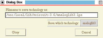
- Load a graphic image File->Import Graphic Image
- This function reads "PPM" (portable pixmap) files, and is the best way to read arbitray graphic images (photos, logos, etc.) into XCircuit. The file must be in "raw" PPM format. Programs like "convert" (ImageMagick), "gimp", etc., can all be used to turn any image into a raw PPM format file. PDF and PostScript files should be converted at a reasonably high resolution to ensure a reasonable printout (actual printed density also depends on the scaling of the graphic image in XCircuit and the scaling of the output page). A good choice is to use at least 150 dpi conversion, e.g., "convert -density 150x150 filename.pdf filename.pnm".
The Tcl/Tk version of XCircuit scripts the conversion so that if the system has the "convert" program, most graphic types will be automatically converted and imported (gif, jpg, etc.).- Load an EDIF format schematic File->Read EDIF file
- This command reads in an EDIF-2.0.0 format schematic file, such as might be produced by another EDA tool such as Composer. Its functionality is incomplete, but it should at least produce a readable schematic and complete library of symbols.
- Run a command script File->Execute script
- This command reads in a script of commands matching the command-line syntax. For the command-line syntax, see the reference pages. There are separate pages for the three different varieties of command-line syntax: TCL, Python, and the original (minimal) version.
- Clear Page File->Clear Page
- Erases everything from the current page. This kind of deletion cannot be undone!
- Console Window File->TCL Console
- This button de-iconifies the TCL console window. The console has several functions. One is to allow direct entry of command-line commands. The other is to keep a printout of all messages generated by XCircuit. The message window at the bottom of the window displays only the most recent message line generated by XCircuit. Error messages will automatically deiconify the console window, since it's undesirable to have potentially important error messages overwritten by other diagnostic or informational messages. When the Console window is present, the menu option changes to "Hide Console".
The Tcl command line syntax accepts any valid Tcl/Tk code. XCircuit functions imported into Tcl are summarized in Tcl-Based XCircuit page.
- Filename The file name to write to. The trailing ".ps" is optional, though any alternative suffixes (such as ".eps") must be included to override the default suffix ".ps". See the item "saving multiple pages", below, for more information.
- Page Label This string names the object, and will also become the label for the page in PostScript (this shows up, for instance, in the page index for Ghostview). By default, the page label takes the name of the filename, without prefixes or suffixes. In a multiple-page file, any page name matching the file name will be appended with a colon and the page number, such that there will be a unique label on each saved page. When writing netlist output, the output netlist filename uses the page label plus the file extension, not the filename (because the file may contain more than one schematic). The page label can also be changed by editing the name of the page in the "page directory" display.
- Scale Page scale only affects the overall scale of the output. The result of scaling is reflected in the X and Y sizes printed below the scale. Changing any one immediately alters the others.
- X/Y Size The maximum width and height of the drawing on the output page, as determined from the overall scale. X and Y cannot be (and never should be!) altered independently.
- Orientation Toggles between "Landscape" and "Portrait".
- PostScript Mode Toggles between "Embedded (EPS)" and "Full Page". "Embedded" is the same as "encapsulated" and would typically apply to single-page figures to be incorporated into a document. Multiple-page xcircuit files (for example, entire schematics) are "Full Page" by definition, regardless of the mode selected, because encapsulated PostScript is not particularly meaningful for multiple-page files. By default, a full-page drawing is centered on the output page. However, this behavior can be subverted by drawing a box to act as the figure's bounding box, and selecting "Options->Elements->Border->Bounding Box" from the menu.
- Sizes This option only appears in "Full Page" mode. There is an entry window in which any arbitray page size can be specified. The "Sizes" label is also a button with a drop-down menu showing a number of standard page sizes.
- Auto-fit This option is only available in "Full Page" mode. When selected, the output will be automatically rescaled to fill the output page (less 1-inch margins). Aspect ratio is preserved, so where the figure width or hight is shorter than the maximum page width or hight, the figure is centered on the output page.
- Saving multiple pages All pages in the current xcircuit environment which have the same filename will be grouped together and saved as a single xcircuit file. An exception is a circuit schematic, in which the circuit hierarchy will be searched for all schematic pages which are subcircuits of the page from which the "Write" command was called. All subcircuit pages will then have their filename entry changed to match that of the current page. Any other pages having the same filename will also be saved. Multiple pages are written in the order encountered, from Page 1 forward. Page ordering can be altered from the page library using the "M" macro.
The existence of a multiple page file and the number of pages is indicated by a check box at the top of the output properties window. If the filename of a multiple-page file is changed, the filename will be changed for all of the pages in the file. To subvert this behavior and separate a single page for saving/printing under a different filename, click the check box. The filename will be reset to a null string, which can be edited to indicate a unique filename for the single page.
Exiting XCircuit
Beginning with XCircuit version 2.3.4 rev. 4, the method to prevent accidental exit (the use of the sub-menu selection "Quit->No Kidding") has been replaced with a check for unsaved changes. If any changes have not been saved, XCircuit will prompt the user for confirmation to exit.
- Quit File->Quit
Xcircuit X-Defaults
- xcircuit*foreground : Black
- xcircuit*background : White
- xcircuit.foreground : Black
- xcircuit.background : White
- xcircuit.gridcolor : Gray95
- xcircuit.snapcolor : Orange
- xcircuit.selectcolor : Gold3
- xcircuit.querycolor : Turquoise
- xcircuit.axescolor : Antique White
- xcircuit.offbuttoncolor : Gray30
- xcircuit.auxiliarycolor : Green3
- xcircuit.barcolor : Tan
- Alternate color scheme
- xcircuit*font : *times-bold-r-normal--14*
- xcircuit.width : 950
- xcircuit.height : 760
- xcircuit.geometry : 950x760
- xcircuit.borderWidth : 2
- xcircuit.borderColor : Red
Xcircuit configuration file (.xcircuitrc)
If a configuration file named ".xcircuitrc" exists in the current working directory (first place searched) or the user's home directory (second place searched) or the xcircuit library directory (last place searched), it will be loaded on startup. The syntax of the .xcircuitrc file is the same as an executable xcircuit script or command-line entry, and is described in the section "The XCircuit Command Line".In addition to the configuration and X-defaults, some XCircuit behavior can be modified through shell environment variables. The environment variables which xcircuit makes use of are listed below:
- TMPDIR
- Directory for temporary (e.g., backup) files (defaults to TEMP_DIR).
- XCIRCUIT_LIB_DIR
- Directory where xcircuit libraries and startup files can be found (defaults to BUILTINS_DIR).
- XAPPLRESDIR
- Directory where the xcircuit application defaults can be found (defaults to RESOURCES_DIR)
- HOME
- Directory where xcircuit will look for startup files, after searching the current directory.
- HOST, HOSTNAME, USER
- Environment variables which xcircuit uses to fill in header information in the PostScript output (HOST and HOSTNAME are equivalent).
PostScript prologue:
- xcircps2.pro PostScript Prologue
The file of PostScript definitions prepended to every saved file.System startup files:
The difference between ".xcircuitrc" and "xcstartup.tcl" in the library is that ".xcircuitrc" will be overridden if a file of the same name exists in a user's current working directory or home directory. "xcstartup.tcl" always runs, although default libraries and fonts listed therein can be forcibly ignored by the user with specific override options. Thus, it is recommended that "xcstartup.tcl" restrict itself to loading fonts and libraries, and that ".xcircuitrc" be used for all other commands. In cases where site-wide definitions are warrented, use the "site.tcl" file.
- xcstartup.tcl Startup script
The master list of fonts and libraries to load on program startup. See the original command-line interface and the Python interface for descriptions of the startup script for the non-Tcl versions of XCircuit.- site.tcl Startup script
This file, if found in the same directory as "xcstartup.tcl", will run as a replacement startup script, and the contents of "xcstartup.tcl" will be ignored. This file is optional, does not come with the distribution, and will not be overwritten by the installation of any distribution. This allows a site-specific startup for XCircuit that will not be lost by subsequent updates of the XCircuit distribution. It should at very least perform the essential functions of the master startup script, loading basic fonts and libraries.- .xcircuitrc Secondary startup script
Commands to run on startup. The syntax of this file depends on whether the source was compiled with the Tcl/Tk interpreter enabled (default), the Python interpreter, or the original command-line syntax.Standard xcircuit library files (technologies)
The following technologies (library .lps files) are loaded by default.The remaining files are put in the system library for access if warranted; they may be added, for instance, to the site-wide "site.tcl" file. They can also be imported in part or in whole using the "Load Technology" or "Library Manager" functions.
- generic.lps
Generic elements pertaining to all schematic types: jumper, dot, circle (port), arrow and arrowhead- analog.lps Basic analog circuit components.
- digital.lps Basic digital circuit components (logic gates).
- avlsi.lps Special circuit components from "Analog VLSI and Neural Systems" (Carver Mead): Simple and wide-range amplifiers with bias port.
- analoglib3.lps Analog circuit elements with parameterized values for SPICE and sim netlist output.
- series74xx.lps The 7400-series digital integrated circuits
- signal.lps Simple elements for signal flow diagrams
- musiclib.lps Library of elements for music typesetting
- lgf.lps Library of elements for loading ".lgf" files from program analog (diglog).
Standard xcircuit font vector files
As listed for automatic loading in the default startup script.
- helvetica.lps
- helveticaiso2.lps
- times_roman.lps
- times_romaniso2.lps
- courier.lps
- courieriso2.lps
- symbol.lps
Standard xcircuit font encoding files
As listed for automatic loading in the default startup script.
- helvetica.xfe
- helveticaiso.xfe
- times_roman.xfe
- times_romaniso.xfe
- courier.xfe
- courieriso.xfe
- symbol.xfe
Extended xcircuit font encoding files
Extends the fonts for ISO-Latin2 (Eastern Europe) and ISO-Latin5 (Turkey). I can generate new encodings for the remainder of the ISO-Latin set, but will not do so until I receive a request. These files are made available in the xcircuit system library, but are commented out of the default startup script.
- helveticaiso2.xfe
- times_romaniso2.xfe
- courieriso2.xfe
- helveticaiso5.xfe
- times_romaniso5.xfe
- courieriso5.xfe
 Back to the xcircuit home page. . .

| email: | 
|
Last updated: October 28, 2025 at 9:40am