The XCircuit Tutorial Part 3: |
|
|
|
IMPORTANT NOTICE: It is necessary for you to have the new (version 3.6 or better) distribution of xcircuit compiled and installed to get the correct behavior in the tutorial. In particular, version 3.6 modifications specifically target large project management, so virtually nothing covered in this tutorial will work correctly without it.The Tcl/Tk-based version of XCircuit is necessary for the proper understanding of this tutorial. A number of functions critical for the management of large projects are written as Tcl scripts and will not be available in the non-Tcl-based version of XCircuit.
If you are not yet familiar with the basic schematic capture features of xcircuit, I insist that you to peruse the basic XCircuit schematic capture tutorial for essential features of the program which will not be reiterated here. This also goes for the original XCircuit tutorial.
When starting a project, it is helpful to define a project directory structure that will define the project. This is a tutorial, not a reference manual, so it defines an example project and example directory structure. Because large, hierarchical, multi-page schematics are most often associated with integrated circuit designs, we will assume this kind of a project.In Tutorial number 2 (the schematic capture tutorial), all schematics and symbols made were placed in a single file. This is really XCircuit's default way of handling a schematic hierarchy: everything goes into one file. If you print the file, each top-level schematic and each schematic that is a descendent of it will be printed on a separate page. To generate a netlist, XCircuit needs to have all these schematics and library symbols loaded at the same time. However, they don't need to be saved in the same file. XCircuit only needs some way to know how to find these schematics when it needs them. This schematic will cover these issues.
The example project defined by this tutorial is a small integrated circuit chip containing a programmable gate array (FPGA) design (for working with standard-cell designs), and a simple low-dropout voltage regulator (LDO) (for working with analog circuits and SPICE models).
The first step in defining a project is to have a useful working .xcircuitrc file in the project directory. The link above contains the following code:
Let's look at this file line-by-line. Line 7 defines XCOps as global, because this variable is used by XCircuit's Tk GUI to define its current state. It is a Tcl "array", which is a hash table defining key-value pairs. It is used in the next line to set key "liboverride", which tells XCircuit not to load the libraries defined in the default system startup script. Instead, we will define our own library setup.
line text 1 #--------------------------------------------------- 2 # .xcircuitrc startup script for large projects 3 # 3/18/06 by Tim Edwards 4 # For xcircuit version 3.6 or newer (Tcl/Tk version) 5 #--------------------------------------------------- 6 7 global XCOps 8 set XCOps(liboverride) 1 9 10 library make analog ;# create empty library 1 11 library make digital ;# create empty library 2 12 library make project ;# create empty library 3 13 library make generic ;# create empty library 4 14 library make analoglib ;# create empty library 5 15 16 library 4 load generic 17 18 config search lib ".:$XCIRCUIT_LIB_DIR" 19 20 library 1 load analoglib3 21 library 2 load digitallib 22 catch {library 3 load project} 23 24 library 4 load analog -replace 25 library 4 load digital -replace 26 library 5 load analoglib2 -replace 27 28 set XCOps(spiceend) false 29 set XCOps(library) project 30 set XCOps(technology) project 31 unset XCOps(liboverride) It is helpful here to clarify the difference between technology files and library pages. A technology file is a file with the extension .lps (for "library PostScript, my designation). The file contains definitions of a group of objects. The file contents are valid PostScript, but since it contains only definitions, running a PostScript display program like ghostview won't show anything (similarly, a Tcl script that contains only procedure definitions doesn't do anything when sourced). A library page is a single page full of objects in XCircuit. A technology file and library page may have a one-to-one correspondence, and often they do. However, it is also possible for a library page to comprise several different technology files, or even for a library page to contain only a portion of the object definitions in a technology file. Note the the two main menu items in the XCircuit "File" menu realted to technology files: "File->Save Technology" and "File->Load Technology". These differ in that the popup window for "Load Technology" has an extra option to select on which library page to place the objects from the technology file. This interface is too simple to allow for splitting technology file objects among several library pages; for that, use the "Library Manager" interface. For this tutorial, we will take the approach of defining one technology for a project, and keeping all object in this file. More about this, below.
Lines 10 through 14 create five empty library pages. This is only necessary because we want the project library page to come before the default xcircuit library pages, for convenience.
Line 16 of the project startup script loads the "generic" XCircuit definitions (objects "jumper", "circle", "arrow", and so forth). Line 18 redefines the XCircuit search path for library files. Starting with version 3.6.12, XCircuit allows variable names to be set in the search path text. Here, line 18 defines the search path as the current working directory, followed by the XCircuit installed system library directory as pointed to by the pre-defined (global Tcl) variable $XCIRCUIT_LIB_DIR. In this case, the tutorial uses files that are provided by the XCircuit distribution. For a specific project, the search path should point to the project directory or some specific subdirectory where schematic libraries are kept, or a different directory where schematic libraries pertaining to a specific technology are kept. Probably you will want a combination (separated in the "config search lib" string by colons) of libraries, including technology-specific standard cell libraries (read-only) and project libraries (read-write). This tutorial assumes the use of a standard cell library and analog parts library defined in $XCIRCUIT_LIB_DIR (and loaded on lines 20 and 21), and a project-specific library in the current working directory (and loaded on line 22). Line 22 uses the Tcl "catch" command to ensure that the XCircuit startup doesn't fail when no project library has yet been created.
Note that the XCircuit command "library libpage load" will always load into the first available empty library if the library page libpage does not exist. To ensure that we get the proper set of library pages even when there are no objects in the project technology file, it is necessary to create all the empty library pages first, before loading the technology files.
Line 28 sets the XCOps array key "spiceend" to value "false". For projects, it works best to define everything as a subcircuit (including the top-level cell) and not to define a top-level circuit until writing the testbench schematic. Therefore, we do not want XCircuit to automatically generate ".end" statements at the end of every file.
Line 29 sets the default library to the project library page "project", and line 30 sets the default technology to the project technology, also called "project". This ensures that all new symbols will end up associated with the project technology, and will all be saved together in the same file (named "project.lps"). As long as the menu function "Write All" is used to save data, updates made to one schematic symbol will become available to all other schematics that use the same symbol.
When defining a project technology file, always load with the "-replace" flag (as in "page load -replace", which resolves naming conflicts by keeping the original object and deleting any new object with the same name. Because XCircuit always keeps symbol information in the same file as the schematic, if any change to a symbol is only saved with that schematic, then no schematics in other files will have access to that change. Then, if multiple schematics using that symbol are loaded in xcircuit at the same time, but each has a different version of the symbol, then XCircuit will create and maintain two separate versions of that symbol. So the "project" technology file becomes the master copy of all library symbols. Each schematic file still keeps its local copies of the symbols it uses, but by using "-replace" during file loads, these local symbol copies get updated with the master copy every time a schematic is loaded.
The GUI interface version of the command-line "-replace" flag is the line below the text entry box for the filename to load that says "Replace From:" followed by a button. The variable set by line 30 of the project ".xcircuitrc" file forces the default button to show "project" as the replacement technology. Likewise, the variable set by line 29 of the ".xcircuitrc" file forces the deefault button for "Target Library:" to display the default library page as "project". Specifically, what these two settings mean is (1) when an object symbol in a file being loaded has the technology "project" and has a name conflicting with a symbol already loaded, the symbol already loaded takes precedence. The .xcircuitrc file ensures that the technology file "project.lps" is read in before anything schematic files are loaded, so symbols in that file always take precedence; (2) when a file is loaded and contains new object symbols (of any technology), they will appear on the "project" library page. Since an individual file is not supposed to contain any object symbols that are not already in the project technology file, any such objects are likely to be ones that were defined with a different technology prefix. If you don't want them on the "project" library page, then remove line 29. This system works well for large projects as long as we stick with the principles:
It is important to know that XCircuit does not assume "-replace" by default when xcircuit is run from the command line. Thus, the line "xcircuit invtest" is equivalent to running "xcircuit" followed by the Tcl command "page load invtest". It is necessary to execute the line "xcircuit -r invtest" to get replacement, the equivalent of running "xcircuit" followed by the Tcl command "page load invtest -replace".
- All symbols that are to be used on more than one schematic must be created with the project technology prefix. You can specify the target technology in the pop-up window when you make an object or create a new symbol for a schematic. Every object carries the technology in the object name as a prefix, e.g., "project::my_object".
- The project library must be saved whenever any object in it has been modified. The modified library will show up on the "Write All" page, and XCircuit will warn if the user is about to quit the program without saving a modified library. However, note that there is no file locking mechanism to ensure that multiple users don't overwrite each other's changes to the project library.
- All schematics must be loaded with the "-replace" option to ensure that modifications to symbols made while editing other schematics are transferred to the new schematic.
- Top-level netlisting of an entire project should be done by a script (invoking xcircuit in batch mode rather than interactively; see below) that ensures that the top-level netlist reads all schematic dependencies with replacement before writing the final netlist for LVS or simulation.
Start xcircuit now (without any options) and go to the library directory (keystroke "L") to confirm the library page layout.Let's look at some of the features of objects used for project schematic symbols. First, to to the library page "analog" (click on the page). Then, push (">" key) into the first symbol on the page, the pMOS field-effect transistor. This object is pretty standard; is has all of the essential attributes that one would normally want to control in a SPICE transistor record outside of the device model parameters: width, length, number of fingers, substrate connection, and model. Note that here the bulk (n-well) terminal node name is a paramter, not a pin. This is still a 4-terminal device, but the bulk (well) node is supplied by appropriately setting the parameter name, and defaults to the node name "avdd". This node name is local to the schematic that instances the symbol, unless the name avdd is declared global somewhere in the schematic. We will come back to this later.
Pop back up to the library ("<" key). Go to the next library ("l" key) of digital standard cells. Push (">" key) into the first object, the inverter (symbol name "INV"). You will note that there are two SPICE output lines for this symbol. The second is the usual one that defines how to write a SPICE call to a subcircuit ("X" record). Like the pMOS object we looked at, it uses parameters, not pins, to define two of the nodes. This gets around the standard problem with digital schematics where the power and ground nodes need to be declared, but are not drawn on every logic gate to avoid cluttering the schematic. The power and ground nodes, by default, are "dvdd" and "dgnd".
The first output formatting info label is a bit different:
spice@1:%F$XCIRCUIT_LIB_DIR/standard_cells.cirThis label is only compatible with XCircuit version 3.6 and newer! The tag part of the label is "spice@1: ". The tag tells XCircuit that this line is applicable when writing SPICE output. The "@" tells XCircuit to write this line outside and before the subcircuit that calls the inverter symbol. In the body of the label, the "%F" tells XCircuit to include the named file that follows. The tag may include any of plain text, Tcl variables, and XCircuit paramters. This tag contains all three. The Tcl variable "$XCIRCUIT_LIB_DIR " is predefined (during compilation and installation of XCircuit) to point to the place where XCircuit's run-time files are installed. In this directory (usually /usr/local/lib/xcircuit-3.6), there should be a file called "standard_cells.cir". This file contains the SPICE transistor-level subcircuit definitions for all of the standard cells.The use of the "%F" escape sequence prevents the standard cell definitions from being read every time a logic gate is instanced. There is a tag "%f" that will be executed for every single instance encountered (not likely to be useful inside a "spice@" line). When using "%F", XCircuit records the file that was read and ensures that it is included in the output SPICE file once and only once.
Edit the text line ("e" key) and move the cursor to the end of the line, just before ".cir". In the byline, you will see that just before the period is the embedded escape "Parameter(voltage)<>". To see how it is used, stop editing the line (mouse button 3 or escape key), pop back to the library ("<" key), and push into the 4th symbol in the library, which looks exactly like the first but has the text "_3V". Here you will see that the first SPICE output formatting label reads:
spice@1:%F$XCIRCUIT_LIB_DIR/standard_cells_3V.cirThe parameter "voltage" has been set equal to the string "_3V", and now the line tells XCircuit include a different file (this one containing subcircuit definitions appropriate for digital standard cells running at 3.3 volts). Note also that in the other SPICE line, the same paramter is used to redefine the name of the subcircuit as written to the SPICE file "X" record.Pop back to the library page for the next part of the task.
Making virtual instances
Of the six library symbols called "INV" on the "digital" library page, the first represents the actual object definition, and the other five (whose symbol names are printed in gray, not black) are considered "virtual instances" of the first. It is easy to make a new virtual instance. Use the middle mouse button to select the first symbol, then type key "V" (shift-v). You will see a new virtual instance of object "INV" at the end of the library.Edit the new virtual instance by pushing the symbol (">" key). Let's make a new "strength 8" inverter (equivalent to 8 standard inverters in parallel). Type "control-p" to get the parameter dialog box. Change the value of "strength" from 1 to 8 (by clicking on the "1" in the value column). Now pop back to the library. If you wanted to use this new symbol in a circuit, you would need to add an entry for the new subcircuit name "INVX8" in the included subcircuit file "standard_cells.cir".
Now, move the new virtual instance to be with the other virtual instances of symbol "INV". Select (middle mouse button) the virtual instance symbol, and type key "M" (shift-m). Note that the instance is following the cursor around. Move the cursor to a point between the strength-4 inverter and the strength-1 3.3V inverter, and click mouse button 1 or 2 to finish.
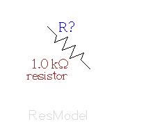
Virtual instances can also be rotated and scaled. Rotated parts can be very convenient for quick schematic drawing. On the library page "analog" there are rotated versions of each device, with the text appropriately counter-rotated so that the rotated device can be used in a schematic with the text always aligned to the direction of the page. Go to the library page "analog". Make a new virtual instance of symbol "ResModel" (key "V"). Rotate this device to 45 degrees with the "r" key. Push this instance, and counter-rotate the text (key "R"). Move the text so that it is not overlapping the component, then pop back out to the library. You should now have a 45-degree rotated resistor symbol in your library. It looks like this:
Now move the rotated resistor symbol to be with the other resistor symbols in the library.
Now, save the library. Choose menu item "File->Save Technology". You will get a dialog box indicating that the target technology file (remember the discussion on technology files vs. library pages above) is "/usr/local/lib/xcircuit-3.6/analoglib3.lps". If you don't have write access to the file's location, then clicking the "Okay" button will produce a message "Library technology analoglib3 is read-only". Whether or not you really want this modified library is entirely up to you.
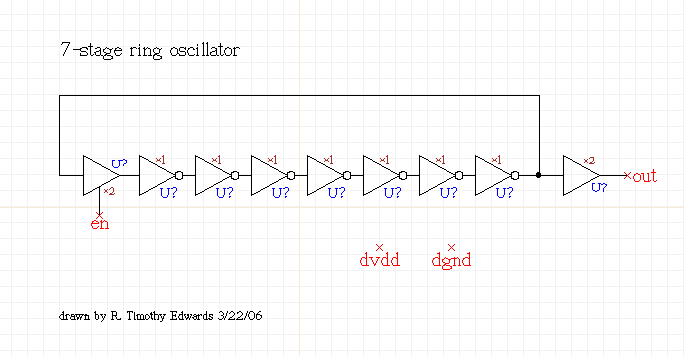
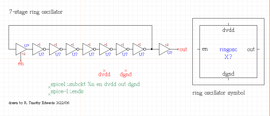
Now that we know a bit about the technology files and symbols, it is time to create a schematic. For the initial task, we will generate a simple schematic to show how all the parts work.Start on Page 1. Take a standard inverter from the digital library, and connect several of them together as shown in the figure below. Add a strength-2 buffer at the output, and a tri-state buffer at the input. Use pin labels for "en" (enable) and "out" as shown. Remember that the power and ground connections for the digital devices are parameters and by default are set to "dvdd" and "dgnd", respectively. These are names local to the subcircuit, and therefore should be defined as pins on the schematic. Make sure that pin labels "dvdd" and "dgnd" are also on the schematic. If you wanted them to be global, you could attach them to the "Vdd" and "Gnd" symbols from the generic parts library. For this tutorial, we will leave them as pins.
Name the schematic "ringosc" by going to the "Write XCircuit PS" dialog box and entering "ringosc" into the Filename: box, and clicking "Apply" (you don't have to write the file yet).
Now, we want to make a symbol corresponding to the schematic. XCircuit version 3.6 has a useful tool for doing all the hard work. Select the menu item "Netlist->Make Matching Symbol". You will get a dialog box that looks like the following:
You will want to make sure that the symbol name is "ringosc", that the target technology is "project", and that the target library page to place the symbol is "project". All of these settings should be ensured by use of the project setup .xcircuitrc file.
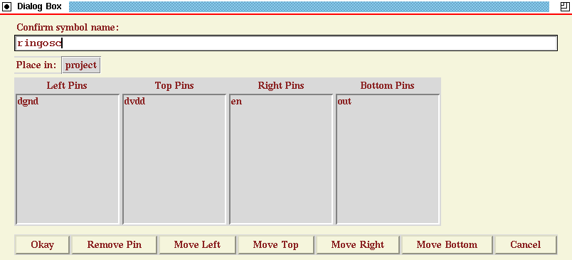
The default symbol generated by "Make Matching Symbol" will be a box (you can change this later if you wish), and the placement of pins around the symbol's bounding box is shown in the columns in the middle. The "Move" buttons at the bottom allow you to rearrange the pins. Put "dgnd" on the bottom, "dvdd" on top, "en" on the left, and "out" on the right by clicking on each pin name and then clicking the appropriate button at the bottom (note that the initial placement of pins is only a convenience; pins in the symbol drawing can be modified at any time after the symbol is created).
When you are done with the initial pin placement, select "Okay" to create the symbol. The first thing you should notice is that some info labels have been added to the schematic. These define the subcircuit definition for the schematic "ringosc" and define the ordering of pins. Several things to note about these info labels:
spice1:.subckt %n en dvdd out dgndThe first line defines the format of the SPICE line. The "%n" gets substituted with the name of the schematic when written to the SPICE output file; in this case, the word "ringosc". The line tag "spice1:" indicates that the line will be the first line output for this subcircuit (before any components internal to the subcircuit), and the line tag "spice-1:" indicates that the line will be the first line output after all components have been written (since there are no lines "spice-2", "spice-3", etc., this will therefore also be the last line written for this subcircuit.
spice-1:.ends
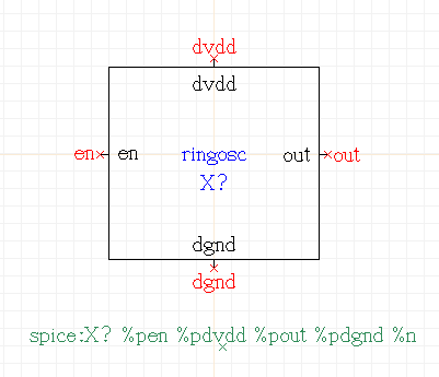
Another change is that the button in the lower left-hand corner of the XCircuit window with the text "Symbol" is now highlighted black and white. Click on it to see the new symbol for "ringosc":
The picture here has been edited slightly from the original to make the symbol a bit smaller.
Go to the library directory and confirm that the symbol has indeed been placed on the library page "project". The symbol name should be "ringosc". If you edit the symbol name (use the "E", or "Shift-e", key to edit labels on the library page), you will get the fully-qualified name, that includes the technology prefix, which is "project::ringosc. If you change the prefix portion of this name, you will change the technology, and the symbol will no longer be associated with the project technology, and will not get written to the project technology file!
Go back to Page 1 (the schematic), and pick one instance of symbol "ringosc" and place it on the page (assuming that you read the first schematic capture tutorial, you will recall that it is legal to have a copy of a symbol on its own schematic; it is ignored when writing the SPICE file to avoid an infinite recursive loop).
Select the "ringosc" symbol and type "control-p". The popup dialog box shows the standard parameters declared for every new project symbol:
These parameters, and their meanings, are as follows:
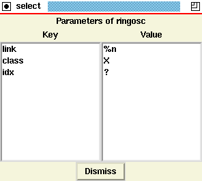
These three parameter names are special to XCircuit in that each of them is handled in a special way by the XCircuit netlister. They are the only parameter key names that are handled differently by XCircuit.
- link
- Defines a link between the symbol and a file that contains the schematic for that symbol. When another schematic file for this project makes use of the "ringosc" symbol from the library, selecting the XCircuit menu option "File->Load Dependencies" will use this link paramter to find the appropriate schematic and load it. By default, the paramter value is "%n", which expands to the name of the symbol + ".ps". If the name of the schematic file is not the same as the name of the symbol, or does not have the extension ".ps", then the value should be changed appropriately. Since all parameters have default and instance values, it is possible to have different instances of this symbol link to different schematics.
- class
- Defines the class of SPICE record written to the SPICE output for this device. Normally you will want to leave this alone. However, it can be useful to change the class, for example, of a MOSFET symbol from "M" to "X" to represent the subcircuit wrapper defining an RF model of a FET device. Another possible use is to convert an entire library of subcircuit symbols from "X" (for SPICE) to "U" (typical for PCB), although generally one would have a completely different library of parts for PCB schematics from that needed for VLSI schematics.
- index
- Defines the component number (or name) for this device. If this is left as the default value "?", then component numbers will be automatically generated for the schematic when the SPICE output is written. You can also auto-generate the component numbers from the "Netlist->Auto-number Components" menu option, or set the component number or name directly. Versions of XCircuit prior to 3.6.56 used the somewhat cryptic parameter key "idx" for the component index. Both keys "index" and "idx" are recognized by XCircuit as indicating component indices.
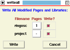
Save the ringosc schematic and symbol for the project by selecting "File->Write All" from the menu. The popup dialog looks like the following:
Click "Write" to write both the schematic page to its own file, and save the modified project technology file. The final schematic drawing is shown below:
There is a fundamental difference between the way XCircuit writes SPICE output in this tutorial and Tutorial 2. In that tutorial, XCircuit wrote its own ".subckt" records and its own "X" records without any specific instructions on how to do so (see the "logic8" schematic). XCircuit has built-in syntax handling for SPICE, but it is limited in a number of respects. When there are no info labels telling XCircuit specifically how to write these records, it will revert to its built-in syntax. The info labels, however, give the user full control over how XCircuit writes the SPICE output, and can be used to define any variant of SPICE, or define a completely different output format. For example, some SPICE versions allow parameters to be passed to subcircuits. XCircuit's built-in syntax can't handle that, but it can be done easily with info labels.
Writing a SPICE Deck
Quit XCircuit and start it again with the simple command line "xcircuit". Go to the library directory. You should see a copy of the symbol for "ringosc" on the library page "Library: project". The library is automatically loaded by the startup file ".xcircuitrc" (see line 22 in the startup script in Task 2). Select "File->Read Xcircuit File" from the XCircuit menu, and load file "ringosc". Now select menu item "Netlist->Write SPICE Netlist". You should get a message saying "spice netlist saved as ringosc.spc".Below is the output file ringosc.spc, with the unused subcircuit definitions removed:
This circuit is useful as-is for the purposes of LVS, and can be included in a testbench circuit that defines the simulation environment and device models. We will discuss testbench schematics later in this tutorial.
line text 1 *SPICE circuit from XCircuit v3.6 rev 15 2 3 * standard_cells.cir, netlists for verifying standard cells 4 * Conrad Ziesler and Tim Edwards, MultiGiG, Inc. 5 * Standard cells are from the IIT standard cell library. 6 7 .subckt TBUFX2 vdd gnd A Y En 8 M1 enb En gnd gnd nfet l=180n w=1.80u m=1 9 M2 enb En vdd vdd pfet l=180n w=3.60u m=1 10 M4 i A vdd vdd pfet l=180n w=3.60u m=2 11 M3 i enb Y vdd pfet l=180n w=3.60u m=2 12 M5 j En Y gnd nfet l=180n w=1.80u m=2 13 M6 j A gnd gnd nfet l=180n w=1.80u m=2 14 .ends 15 16 .subckt BUFX2 vdd gnd A Y 17 M1 x A gnd gnd nfet l=180n w=0.90u m=1 18 M2 x A vdd vdd pfet l=180n w=1.80u m=1 19 M3 Y x gnd gnd nfet l=180n w=1.80u m=1 20 M4 Y x vdd vdd pfet l=180n w=3.60u m=1 21 .ends 22 23 .subckt INVX1 vdd gnd A Y 24 M1 Y A gnd gnd nfet l=180n w=0.90u m=1 25 M2 Y A vdd vdd pfet l=180n w=1.80u m=1 26 .ends 27 28 .subckt ringosc en dvdd out dgnd 29 X1 dvdd dgnd int5 out BUFX2 30 X2 dvdd dgnd ext12 int5 INVX1 31 X3 dvdd dgnd ext11 ext12 INVX1 32 X4 dvdd dgnd ext10 ext11 INVX1 33 X5 dvdd dgnd ext9 ext10 INVX1 34 X6 dvdd dgnd ext8 ext9 INVX1 35 X7 dvdd dgnd ext6 ext8 INVX1 36 X8 dvdd dgnd int5 ext7 en TBUFX2 37 X9 dvdd dgnd ext7 ext6 INVX1 38 .ends
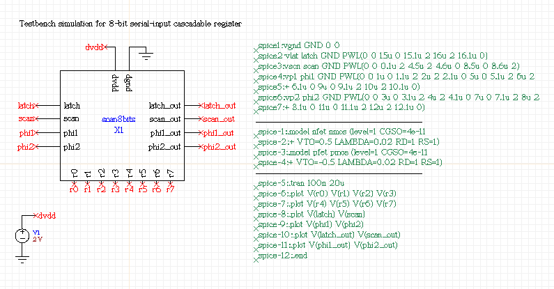
First we must address the task of creating a schematic with several layers of hierarchy. There are a number of useful tools and tricks in XCircuit that will help you with the task, and we will cover these topics as the opportunity arises.In this task, we will design an 8-bit, serial loading register. Start a new session of XCircuit. You may want to delete the "project.lps" file (containing the symbols made in the previous task) first, although this is not necessary.
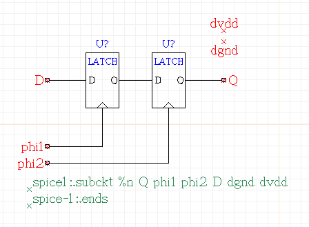
The first schematic to draw, on Page 1, is a D flipflop, as shown in the figure below.
As for the previous task, draw all of the components, labels, and wires in the figure, but let the menu item "Netlist->Make Matching Symbol" draw the info labels for you, and make the standard parameters. Also as before, the power supplies "dvdd" and "dgnd" are drawn as (unattached) pins so that they will show up as pins on the symbol. Name the symbol "dff" when you make the matching symbol.
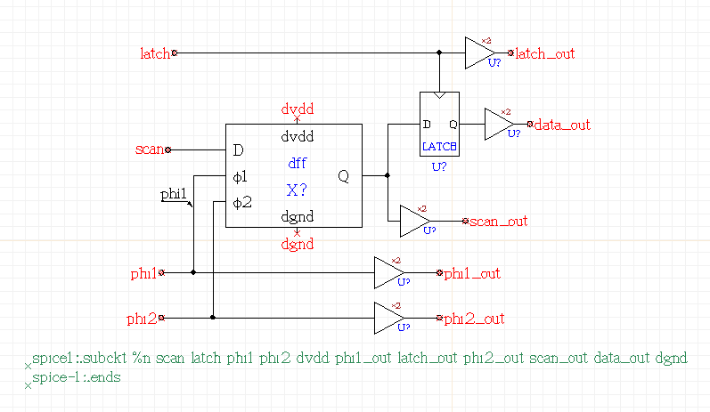
On Page 2 of XCircuit, make the second schematic, as shown below. It instantiates the D flipflop that was just made and placed on the "project" library page. When making the symbol for this schematic, name the symbol "scan_register".
Finally, draw the top-level schematic on Page 3 of XCircuit. To make the parallel outputs, you can use a convenient shortcut. After placing the eight scan register symbols, draw the wire for output pin "r0" only, and make the pin label "r0". Select the wire and label, and type "c" for "copy". Now, while you are dragging around the first copy of the pin and wire, type the key "i". This executes the Tcl script command "xcircuit::autoincr", and has the effect of changing the text of the label that is being dragged around from "r0" to "r1". Place the pin and wire for network "r1" with the left mouse button, then type "i" again. Continue in this manner until you have placed all of the pins.
Advanced use note: It is very easy to generate hundreds of pins using the auto-increment feature. For example, if you select and copy all of the eight pins that you made, then typed the command "xcircuit::autoincr 8" on the console command line, you will find that you now have pins labeled "r8" through "r15". Versions of XCircuit beginning around 3.6.120 have a GUI interface from the popup window generated from the menu selection "Text->Modify...". This interface has auto-increment and -decrement, as well as text search and replace.
Make the top-level schematic into a symbol as well, and name the symbol "scan8bits".
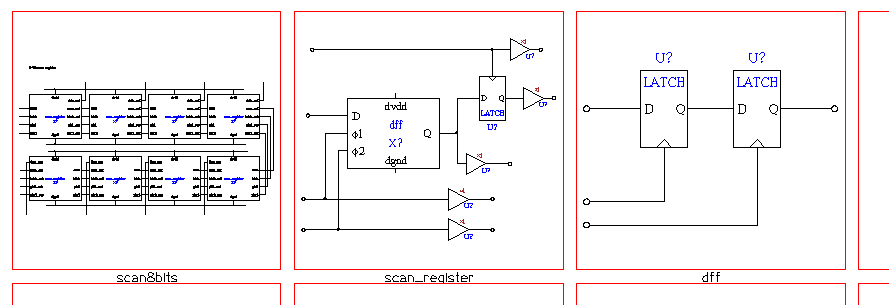
Now that you have generated all three (hierarchical) schematics, the project library page should have all three symbols that represent the three schematics just drawn. The "project" library page should contain at least the objects shown below.

The Page directory looks like the following:

Now, make sure that all of these pages and the technology file have been written using the menu option "File->Write All...". Although the pages were not named, the "Make Matching Symbol" script should have copied the symbol names (without the technology prefix) to the schematics, and "Write All" should write three separate 1-page files. If you followed the naming conventions suggested above, the three files should be "dff.ps", "scan_register.ps", and "scan8bits.ps".
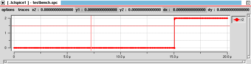
Having written these files, you should be able to do "File->Quit" to quit XCircuit without getting a dialog box, since there are no changes to any pages or libraries since the last file write. Now, start xcircuit again with the command line "xcircuit scan8bits". Go to the page directory. You will see that only the file "scan8bits.ps" was loaded. Write a SPICE output file for this schematic by selecting "Netlist->Write SPICE netlist" from the XCircuit menu. Look at the resulting output file scan8bits.spc, which is shown below:
This is only a partial netlist representing the schematic on Page 1. XCircuit will not write output for any circuit that is not loaded and visible in the page directory. To get the full netlist, and to see all the schematic subcircuits that make up the "scan8bits" top-level circuit, go to the XCircuit menu and select menu item File->Load Dependencies. Then go to the page menu, where you should see all three schematic pages. Go back to Page 1, and choose the menu item Netlist->Write SPICE netlist. Once again, you will get a file called scan8bits.spc, but this time it is a complete netlist. Once again, the file minus the unused standard cell subcircuits, is shown below:
line text 1 *SPICE circuit from XCircuit v3.6 rev 19 2 3 .subckt scan8bits latch phi1 scan phi2 dvdd dgnd scan_out phi1_out phi2_out latch_out r6 r7 r1 r2 r3 r4 r5 r0 4 X1 int39 int40 int41 int42 dvdd phi1_out latch_out phi2_out 5 + scan_out r7 dgnd scan_register 6 X2 int35 int36 int37 int38 dvdd int41 int40 int42 7 + int39 r6 dgnd scan_register 8 X3 int31 int32 int33 int34 dvdd int37 int36 int38 9 + int35 r5 dgnd scan_register 10 X4 int46 int45 int44 int43 dvdd int33 int32 int34 11 + int31 r4 dgnd scan_register 12 X5 int27 int28 int29 int30 dvdd int44 int45 int43 13 + int46 r3 dgnd scan_register 14 X6 int23 int24 int25 int26 dvdd int29 int28 int30 15 + int27 r2 dgnd scan_register 16 X7 int19 int20 int21 int22 dvdd int25 int24 int26 17 + int23 r1 dgnd scan_register 18 Xtest scan latch phi1 phi2 dvdd int21 int20 int22 19 + int19 r0 dgnd scan_register 20 .ends The netlist above is appropriate for purposes of comparing the schematic against a layout (layout vs. schematic, or "LVS"). However, it still is missing vital information required for simulation. A schematic of this type is usually referred to as the "device under test", or "DUT", and is instantiated inside a separate schematic called the "bench test" schematic. This is what we will do in the next task.
line text 1 *SPICE circuit from XCircuit v3.6 rev 16 2 3 * standard_cells.cir, netlists for verifying standard cells 4 * Conrad Ziesler and Tim Edwards, MultiGiG, Inc. 5 * Standard cells are from the IIT standard cell library. 6 7 .subckt BUFX2 vdd gnd A Y 8 M1 x A gnd gnd nfet l=180n w=0.90u m=1 9 M2 x A vdd vdd pfet l=180n w=1.80u m=1 10 M3 Y x gnd gnd nfet l=180n w=1.80u m=1 11 M4 Y x vdd vdd pfet l=180n w=3.60u m=1 12 .ends 13 14 .subckt LATCH vdd gnd CLK D Q 15 M1 cb CLK gnd gnd nfet l=180n w=0.90u m=2 16 M2 cb CLK vdd vdd pfet l=180n w=0.90u m=4 17 18 M3 x2 D vdd vdd pfet l=180n w=0.90u m=2 19 M4 qb cb x2 vdd pfet l=180n w=0.90u m=2 20 M5 x4 D gnd gnd nfet l=180n w=0.90u m=1 21 M6 qb CLK x4 gnd nfet l=180n w=0.90u m=1 22 23 M7 x5 Q vdd vdd pfet l=180n w=0.90u m=1 24 M8 qb CLK x5 vdd pfet l=180n w=0.90u m=1 25 M9 x7 Q gnd gnd nfet l=180n w=0.90u m=1 26 M10 qb cb x7 gnd nfet l=180n w=0.90u m=1 27 28 M11 Q qb gnd gnd nfet l=180n w=0.90u m=2 29 M12 Q qb vdd vdd pfet l=180n w=0.90u m=4 30 .ends 31 32 .subckt dff Q phi1 phi2 D dgnd dvdd 33 X1 dvdd dgnd phi2 int8 Q LATCH 34 X2 dvdd dgnd phi1 D int8 LATCH 35 .ends 36 37 .subckt scan_register scan latch phi1 phi2 dvdd phi1_out latch_out phi2_out scan_out data_out dgnd 38 X1 dvdd dgnd int18 data_out BUFX2 39 X2 dvdd dgnd latch latch_out BUFX2 40 X3 dvdd dgnd latch int19 int18 LATCH 41 X4 dvdd dgnd phi2 phi2_out BUFX2 42 X5 dvdd dgnd phi1 phi1_out BUFX2 43 X6 dvdd dgnd int19 scan_out BUFX2 44 X7 int19 phi1 phi2 scan dgnd dvdd dff 45 .ends 46 47 .subckt scan8bits latch phi1 scan phi2 dvdd dgnd scan_out phi1_out phi2_out latch_out r6 r7 r1 r2 r3 r4 r5 r0 48 X1 int39 int40 int41 int42 dvdd phi1_out latch_out phi2_out 49 + scan_out r7 dgnd scan_register 50 X2 int35 int36 int37 int38 dvdd int41 int40 int42 51 + int39 r6 dgnd scan_register 52 X3 int31 int32 int33 int34 dvdd int37 int36 int38 53 + int35 r5 dgnd scan_register 54 X4 int46 int45 int44 int43 dvdd int33 int32 int34 55 + int31 r4 dgnd scan_register 56 X5 int27 int28 int29 int30 dvdd int44 int45 int43 57 + int46 r3 dgnd scan_register 58 X6 int23 int24 int25 int26 dvdd int29 int28 int30 59 + int27 r2 dgnd scan_register 60 X7 int19 int20 int21 int22 dvdd int25 int24 int26 61 + int23 r1 dgnd scan_register 62 Xtest scan latch phi1 phi2 dvdd int21 int20 int22 63 + int19 r0 dgnd scan_register 64 .ends
 Back to the xcircuit home page. . .

| email: | 
|
Last updated: October 28, 2025 at 9:41am