

 This project and its contents are given to the public domain
 by the author, under the Creative Commons---Attribution---Share Alike license.
Written by Tim Edwards
Poolesville, Maryland
December 10-11, 2015
by the author, under the Creative Commons---Attribution---Share Alike license.
This project got a wonderful writeup on the 3ders.org website. Many thanks to Alec and the 3ders.org team!
Introduction
Motivation
How it Works
Getting Started
Hardware
Printed Parts
Hardware Assembly
Software
Firmware
Calibration
Testing
Videos from calibration runs
Future Projects
This web page gives full instructions for implementing a novel dual extruder version of the MakerGear M2 3D printer. The MakerGear M2 is one of the best 3D printers on the market, and that has not changed for the several years that it has been on the market. I've had my M2 since January 2013, and I've enjoyed every minute of it (well, okay, that can never be said for anything mechanical, but the joys have been many and the disasters, few).There are several compelling reasons why I bought myself a MakerGear M2 as opposed to some other machine. For one, it is a very solidly build piece of equipment. Unlike many 3D printers that use steel rods for the rails, the MakerGear team used precision linear bearing guides firmly bolted onto a steel frame. This gives it a high degree of stability and a low degree of vibration, and it can stay in perfect calibration day after day after day. I once marveled that I packed my M2 into a box and drove it to my kid's school for a demonstration, unpacked it, set it up, and found that it was all still in perfect alignment and ready to print.
Another reason to get the MakerGear M2 is that it has open hardware, open firmware, places no restrictions on the type of filament you can purchase and use, and is generally a very good machine to modify and experiment with. And the good folks at MakerGear are very friendly toward people who tinker with their M2s, providing encouragement and even the occasional piece of extra hardware. Their M2 kit version (which I purchased) comes with so many extra machine screws and spare parts that I need an extra organizer to hold them all.
Finally, there is the MakerGear forum, a support group of many talented M2 owners with whom I share ideas and opinions. Help is only a post away, and a response is usually only minutes in coming. These are my friends and my community.
If you wish to make comments about this project, please post to this forum thread about it.
In July of 2014, MakerGear offered an experimental dual extruder kit to those of us on the forum who were interested. I was one of the first batch of beta testers. The picture below shows the MakerGear dual extruder, although in the picture I have replaced the original drive mounts with new ones that I printed in translucent blue PETg, with guides for the filament tubes.
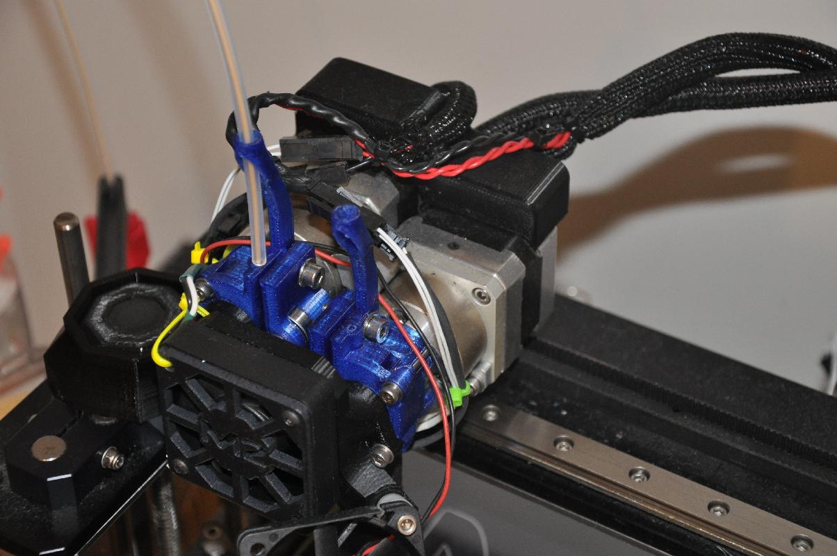
MakerGear chose a fairly traditional dual extruder architecture, in which the stepper motors are mounted side-by-side. The motors are slightly offset in height, to allow the drive mounts to fit as close together as possible. The distance between the two nozzles is about 30mm. Incredibly, they managed to make this design work without losing any bed area (at least for the left extruder. The right extruder doesn't quite make it to the left side of the bed).So with such a nice dual extruder setup, why would I want to change anything? Well, once I started working with dual extruder prints, it became clear that this general architecture of having two extruders fixed side by side has its limitations. For one, I usually print using PETg plastic, which tends to ooze and drip a lot more than the PLA plastic that is so popular with 3D printers. Also, the right extruder does tend to drag across the print, and if the print ever warps or curls up the slightest bit, it is in danger of catching on the other extruder and ripping the print off of the bed (among the worst-case scenarios). So I would tend to push the nozzle up out of the way most of the time when I was using only one extruder to print. But that meant readjusting the right side nozzle every time I wanted to do a dual color print, a minor hassle, but a hassle regardless.
So what to do about all that dripping? I considered a few possibilities, such as a needle valve in the nozzle (this has been done on the Robox printer), or mechanically moving each extruder up and down into position. But those ideas were beyond my meager mechanical skills, or were difficult to implement with the linear rail architecture of the M2. I actually got partway into a project which I had thought of that put the dual extruder assembly on a hinge so that it would rock back and forth, allowing one nozzle to rotate into place while the other one would rotate out of the way and onto a plate where it could stay parked. I even had a system by which the action of retracting the filament would cause the assembly to rotate, avoiding the need for an extra motor. Unfortunately, the major problem was the lack of vertical space. To get the assembly up on top of a hinge put the nozzles too far up for the bed to reach (without crashing into the top of the frame). By making the hinge small enough for the nozzles to be mounted low enough to reach the bed properly, the hinge was too weak if made of anything other than metal. On top of that, it was difficult to keep the passive rocking system firmly in place.
So one day in October 2015, after more than a year of having the MakerGear dual extruder, I came upon the alternative idea of having two separate single extruders working on the same linear rail. From my original idea of the hinged, rocking mechanism, I had firmly in mind that whatever solution I came up with must keep the restriction of requiring no additional motors, actuators, or switches, but should be able to be wired up with the existing wiring to the electronics box. Other dual extruder ideas I had seen consisted of additional hardware, and that required additional wiring, additional electronic components, and a good deal of firmware writing, leading to incompatible and non-upgradeable firmware. I wanted something that could be done as a weekend project with no particular expertise (other than that usually held by 3D printer owners), and no special hardware that couldn't be either readily purchased or printed.
I found my answer in a magnetic coupling mechanism. I decided that what really mattered for horizontal alignment was that the same position on the belt must always be aligned to the same position of the nozzle. If instead of clamping the whole extruder assembly to the belt, you left the extruder assembly free to slide along the rail, and put a clamp on the belt separately, and hold the two together with magnets, then as long as the magnets stay firmly in place, the extruder assembly should move together with the belt as precisely as if it were firmly bolted to it. Of course, that was the theory, and I would need to experiment to see if it was true that the motor yanking the extruder around would not yank the magnets apart. The points in favor of this idea were that the linear rail is quite smooth and low on friction, while the magnets would only be able to be decoupled in the direction of their axis, which has the strongest magnetic force.
I call this architecture the "twin extruder" architecture rather than the "dual extruder" to emphasize that while both extruders look exactly alike, they operate independently.
Here is a simplified top view showing the architecture of this novel dual extruder system. It is a view of the MakerGear M2's top frame and X-axis belt. There are two extruders, left and right, which are bolted onto mount plates that hold them firmly to the X-axis linear rail, but critically, not to the belt. Instead, there is a printed piece, the belt grip, that is the only thing attached to the belt.

Because much of the mechanism is not easy to see in action, it is best illustrated by a few pictures showing the steps that allow the right and left extruders to maintain independent motion while requiring no additional electrical or special mechanical hardware. The method is done simply by using gcode instructions to position the extruders at the right place to switch from one to the other. This is how it works:Step 1. Initial position. The left and right extruders are "parked", which means that each sits as far to the right or left as possible, and the nozzle sits upon a "wipe plate" or "parking plate". By having this plate directly under the nozzle, it prevents the nozzle from being open to the air and allowing filament to ooze or drip out; the nozzle maintains pressure and is always ready to print.
Each extruder is magnetically coupled to its side of the printer by a single magnet. In this drawing, the belt grip is all the way to the left, so it is connecting the belt to the left side extruder.

Step 2. The X-axis motor pulls the left extruder to the right. Because the belt grip connects to the extruder with two magnets, it is stronger than the magnet holding the extruder to the left side, and pulls it off. The left extruder is now active and printing.As the extruder is pulled off of the parking plate, it passes over a wiper that cleans off any filament that may have oozed out during travel, preparing the extruder for immediate printing.

Step 3. Time to switch extruders. The left extruder moves all the way to the right until it stops against the parked right extruder. At this point, the left extruder is physically prevented from traveling any further to the right.

Step 4. Although the left extruder cannot move any further, the belt grip can. By continuing to move the X stepper motor further right, the belt grip is yanked off of the left extruder, breaking the magnetic connection. By carefully calibrating the distance to the right side, the belt grip can continue until it magnetically engages the right extruder. The left extruder is now free-moving.

Step 5. The X-axis stepper now moves the right extruder out of the parked position. The nozzle wipes off on the wiper as it comes off of the parking plate. The right extruder cannot start printing until the left extruder is parked, but the left extruder is not connected to the belt. So it is the right extruder's responsibility to park the left extruder. The right extruder moves all the way to the left, pushing the left extruder all the way to the left and into the parked position, where it once again becomes magnetically connected to the left side.

Step 6. Having accomplished the parking maneuver, the right extruder is now active and ready for printing.

Step 7. To switch from the right extruder back to the left extruder, the same procedure from step 2 is done, in mirror image.
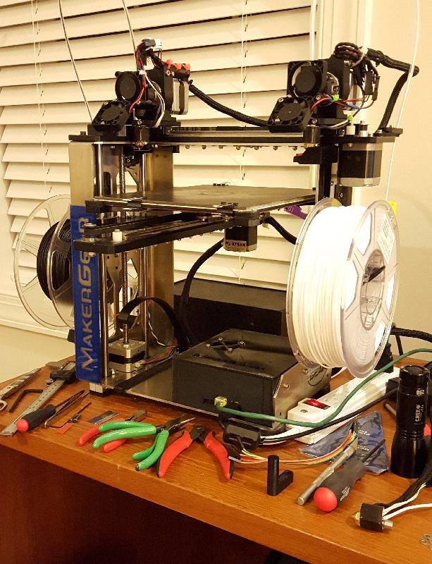
Okay, so you have read this far, and you have taken my advice (which I'm just giving to you now) to read through the whole thing and understand all the pros and cons, and you have come back to this section and decided that yes, you want to build this project.As stated earlier, this system is designed specifically to avoid having extra electronics, extra wiring, extra motors, solenoids, or other electromechanical systems, or special firmware or software to run. However, it still requires that you be comfortable with field-stripping your M2 and putting it back together again, and the use of a soldering iron or crimp tool is not out of the question. It is assumed that since you are willing to launch into a DIY project, that you have the full complement of basic tools such as screwdrivers, allen wrenches, pliers, tweezers, hobby knives, and so forth. Nothing particularly unusual will be needed for this project. One specific item that is needed is a non-metric 3/32 inch allen wrench, and that can probably be avoided if necessary.
This probably is a "goes without saying" statement, but make sure that you get all parts of the project printed before you start breaking down your M2. A necessity of developing this project from scratch is that I had to field-strip and reassemble my M2 multiple times, and I'm sure you don't want to have to do that unnecessarily.
- 24 0.1" diameter cylindrical neodymium magnets.
N50 cylinder magnets, set of 10 magnets. These can be purchased from "Super Magnet Man", part ID Cyl0053.Buy extras; they fit tightly in the holes, so they will not come out without destroying the printed part they're embedded in. Plus, they're fun to have sitting on your desk where you can play with them all day. Or design other magnet-based projects. Cost comes to 25 cents each.
This used to be avaliable on Amazon from the same supplier, but apparently has been discontinued.
Because the magnets are impossible to get out of a printed piece, don't put the magnets in the printed parts until you've fitted the part and made sure it's good.
- 1 or 2 MakerGear v4 upgrade kits.
Available directly from MakerGear: go to the MakerGear upgrades page, and select "Single v4 extruder upgrade" (which hopefully is in stock). If you already have an M2 with the single v4 extruder, you'll need one extra of these. If you have any other M2 model, you'll need two. If you already have the M2 dual, you'll end up with two extra v4 hot-ends, so make sure you order something you can make good use of, like a hardened steel nozzle or a different nozzle size. It never hurts to have spare hot-ends lying around. Cost of the v4 upgrade kit (each) is $99.
The main point of getting the v4 upgrade kit is to obtain two v4-compatible metal mount plates. If you have the capacity to mill these yourself, go right ahead.
- Linear rail block (carriage).
MakerGear sells these on the "Spare parts" page. Go to the MakerGear Spare Parts page, and select "Replacement Carriage for either X or Y Rail on M2". Cost is $25.
- Fans.
The twin extruder setup necessitates having the full extruder fan plus bed fan setup duplicated on each extruder assembly. Per the traditional MakerGear setup, the extruder fan is 12V while the bed fan is 24V. If you follow my plan, I use 40mm x 40mm fans for both the extruder and bed fans, and I use a 12V voltage regulator to drive the 12V fans off of the 24V supply, rather than connect them in series. See the discussion below.
Fans can be obtained from many places; probably the best is to get them from MakerGear because they will come with the right kind of connectors for attaching to the cable harness ends (although note that older M2 cable harnesses had a simple, unlatched 2-pin connector). I got my fans through Amazon:
12V fan ($5.99 each at the time I got them)
24V fan ($6.80 each at the time I got them)
Fans are cheap and take a lot of beating and tend to get poor reviews, but these are running on my printer now and seem to be no better or worse than any other. They both yield excellent air flow.
- 26 gauge brass plate
I had some scrap brass plate lying around my workspace, but it can also be obtained from a number of places. The thickness used in the bracket models is 26 guage, or 0.4mm, or 0.016". Here's one source:
McMaster-Carr 260 Brass 0.016" Miniature Strips, unpolished, part 8859K671, 0.5" wide by 12" long. Price as of this writing, $1.37 each.It might be preferable to get a much wider (not thicker) plate and cut it, punch it, and bend it into shape to make an all-metal parking plate and bracket.
If you have only a single extruder system and are building this project as your first foray into dual extrusion, then there are a few additional parts that you will need to complete the parts list. These are all parts that are unnecessary if you already have a dual extruder setup.
- Extruder stepper motor.
If you have a single extruder machine to start with, then you will need another extruder stepper motor, since those don't come with the v4 upgrade kit. MakerGear sells their extruder stepper separately; go to MakerGear motors page, and select the Kysan Geared Stepper Motor (5:1)(Ext for M2). Cost is $55.
- Wire harness.
You will need a second wire harness, which connects to the electronics controller board (i.e., RAMBo) as described in the MakerGear instructions for the dual extruder. Extra wire harnesses are available from MakerGear, although you will need to ask for one by request, as currently I don't see any listed for purchase on the website. Wire harnesses can of course be made by hand, but I don't immediately have a parts list. I could work one up if necessary, by request.
- Teflon filament guide tubing.
You should be able to find these on Amazon under "2.0 mm ID (inner diameter) Teflon Tube", usually specified for 3D printers. Or you can go with cheaper tubing (teflon is best for flexible filaments, though). You will need about a 50cm length of it.
MakerGear also sells these on the "Spare parts" page. Go to the MakerGear Spare Parts page, and select "M2 Extruder Tubing - 18 inch piece". Cost is $5.
- 5x16x5 shielded bearing.
Model 625ZZ, this is the bearing that presses the filament against the extruder gear.
- M4 shoulder screw, 14mm shoulder length.
This is the screw that holds the bearing on the printed filament drive. The "shoulder length" is the length of the unthreaded part.
- 2x M4 x 35mm machine screw.
These are the machine screws that clamp the motor mount onto the motor. You will also need M4 nuts and (preferably) washers.
Finally, it's a good idea to have an assortment of mainly M3 machine screw hardware, and also some shrink tubing and cable ties to keep everything neat and tidy.Total project cost estimate is around $230 (plus tax and shipping on various orders) if you start with an M2 having a single v4; cost is around $260 if you start with the dual extruder, the extra cost reflecting the fact that you end up with extra v4 hot-ends that are spares. Getting the v4 mount plates by ordering an entire v4 upgrade kit is the most expensive part of the project if you already have a dual extruder; if you can manage to get the mount plates sold separately, the total cost should be around $100 or so.Compare this project cost starting from a single v4 (about $230) to the price MakerGear sells the dual extruder upgrade ($300). Considering that you are printing a number of key parts instead of purchasing them, the costs are roughly equivalent. The bulk of the cost is in the specialized hardware, that is, the stepper motor and hot-ends.
Note that these are not specifically STL files, but links to the github page with the part. From the github page, download the part by clicking on the "Raw" button.
File Size Notes Dual Belt Clamp With Striker 7.22MB 1 Extruder Motor Mount r3 9.75MB 2 Single Filament Drive 789kB 3 Universal Spool Holder 10MB 4 Dual Right Spool Holder 5.59MB 5 Dual Z Knob 272kB 5 Right filament guide 566kB 5 Standard fan bracket 23kB 6
Important Notes:
- You do not need to print this belt clamp; it is one of the sources and is imported into the openSCAD file below and modified to generate the magnetic belt clamp.
- The motor mount is not the one I used, but should be equivalent. Very important: Print this mount IN REVERSE (flipped across the X axis). You will need to print two of these (both reversed).
- The filament drive, like the motor mount, must be printed IN REVERSE (flipped across the X axis). You will need to print two of these (both reversed).
- This spool holder is an improved version that fits both sides, as well as being small enough to accomodate the spools of most if not all brands of filament, created by Corey Renner in response to the needs of this project (thanks, Corey!). Use this in preference to the MakerGear version listed below it.
- The right spool holder, right filament guide, and low-profile Z knob are only needed if you do not already have the dual extruder option. I think that this project will work fine with the original Z knob, though. I'm posting the link to the lower-profile dual version Z knob, just in case.
- There are many alternatives to the standard fan bracket on Thingiverse and elsewhere.
These files have also been posted to Thingiverse
File Name Revision Size Date Notes belt_clamp.stl Magnetic belt clamp 0 22.1MB December 11, 2015 2 mount_coupling.stl Mount plate coupling block 0 378kB December 11, 2015 1 left_parking.stl Left side parking block 0 186kB December 11, 2015 2 right_parking.stl Right side parking block 0 226kB December 11, 2015 2 wipe_plate_left_simple.stl Left side wipe plate, no wiper 0 195kB December 11, 2015 2 wipe_plate_right.stl Right side wipe plate with wiper 0 115kB December 11, 2015 2 single_drive_with_guide.stl Single v4 filament drive, with filament guide holder 0 3.09MB December 23, 2015 3 Narrow motor mount (thing 1229641) Narrow motor mount by Corey Renner 0 488kB December 28, 2015 4
Important Notes:
- Print two mount couplings, one of them as-is, and one IN REVERSE (flipped across the X axis).
- Print one each of all the other models.
- You may prefer this filament guide design, which is just the MakerGear single filament guide with a holder for the filament guide tube added.
- You may prefer this motor mount designed by Corey Renner (the link is to Thingiverse). It is significantly less bulky than the original and recovers additional space on the X axis for the left extruder. It accomodates the MakerGear wire junction box on top (link to the junction box can be found on the Thingiverse page). Because it is bolted directly to the motor, it does not allow the motor to rotate in the mount.
These files have also been posted to Thingiverse
File Type Revision Size (KB) Date belt_clamp.scad Magnetic belt clamp 0 1.5kB December 11, 2015 mount_coupling.scad Magnetic mount coupling 0 0.9kB December 11, 2015 left_parking.scad Left side parking block 0 0.9kB December 11, 2015 left_parking_template.dxf Left side parking outline template 0 5.5kB December 11, 2015 right_parking.scad Right side parking block 0 1.3kB December 11, 2015 right_parking_template.dxf Right side parking outline template 0 5.5kB December 11, 2015 wipe_plate_left_simple.scad Left wipe plate without wiper 0 2.0kB December 11, 2015 wipe_plate_right.scad Right wipe plate with wiper 0 2.7kB December 11, 2015
Notes:
- The DXF files are shape outline templates that are imported by the openSCAD files.
- The belt clamp and mount coupling files import and manipulate the original belt clamp model for the MakerGear dual extruder, so you will need to download that from github (see above) if you want to compile the openSCAD files.
- Files importing external STL files are very slow to compile. . . be patient.
- You should not need to compile any of these sources, but they are here in case you think you can do better! All improvements are welcome, if you will kindly post them back to me.
Step 1.
Purchase all of the necessary hardware, and print all of the needed printed parts before disassembling the M2 for the project. Don't miss the important notes that you need to print reversed models of the motor mount and filament drive, and one of the mount coupling models needs to be reversed so that you have a mirror-image pair.The motor mount STL file is already upside down, so if you flip it across the Z axis, you get it both in the reverse direction needed for the project, and in the correct orientation for printing.
The filament drive needs to be printed with support. After printing, the filament path through the drive needs to be bored out with either a 2mm wire or drill bit to ensure that the filament will move smoothly through the drive without catching on any rough spots. The modified filament drive model with the socket for the filament guide tube is preferred over the original MakerGear model (and also needs to be printed in reverse). Note that if you wish to add an inductive Z-probe to the twin extruder, then use the filament drive with the Z-probe bracket (found near the bottom of this page) for the left extruder. It also needs to be printed in reverse. Photos of the project do not show the filament drive with the bracket.
If you do not have the MakerGear dual extruder upgrade, then you will want to also print the right side spool holder and filament guide, so you have somewhere to put your second spool of filament when it comes time to start printing in two colors.
Step 2.
If you have a pre-existing single v4 extruder setup, you will need to dismantle the extruder assembly and remove everything from the mount plate. If you have a MakerGear dual extruder, it's not necessary to disassemble anything yet.Step 3.
Bolt the mount couplings to the mount plates. These will have to be taken off later to install them over the belt. However, it's a good idea to have them bolted so you can be sure everything is facing the right direction when the magnets are inserted, and also so that the machine screws will help keep the model from splitting, although I didn't encounter any problems with that.

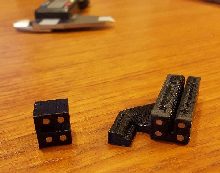
Printed parts (viewed from top):
- A: Left parking block
- B: Left mount coupling (installed on underside of mount plate)
- C: Belt clamp
- D: Right mount coupling (installed on underside of mount plate)
- E: Right parking block
Both mount plates will be installed backwards relative to the way they are positioned on the MakerGear single v4 extruder assembly. The side of the plate that has a 45 degree angle on it should be on the right for both plates. However, the mount coupling screws into the left side of the left plate and the right side of the right plate (see drawing above; note that the mount couplings are connected to the underside of the mount plates in the position shown).Mount couplings connect with the same M2 machine screws and nuts that held the original belt clamp.
Install the magnets in the belt clamp, mount couplings, and end blocks. Make sure all parts are facing the direction in which they will be installed on the M2 (as in the drawing), and insert all magnets facing the same direction (this is not strictly necessary but is the easiest way to make sure it doesn't get screwed up. If any of your magnets is repelling, you're in trouble).
The holes are purposely designed slightly undersized for the magnets. The best method is to take a 3/32" (yes, non-metric, because it's closest to the 0.1" diameter of the magnets) allen wrench and insert it straight into the hole to bore it out, then pull it straight out (do not twist, or the hole will end up too large and the magnets will be loose). Then the magnet should fit firmly in the hole. Press against a flat surface to make sure the magnets are just flush with the surface of the printed part. Be careful not to push them too far in.
Printed parts: belt clamp and mount coupling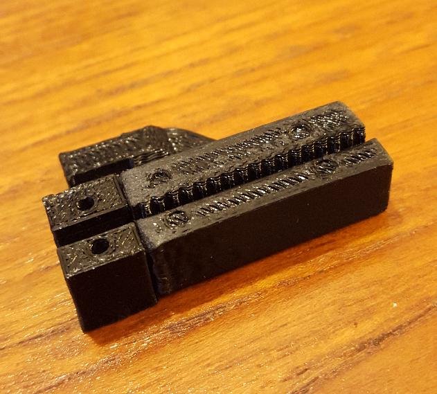
The mount coupling magnetically attached to the belt clamp.Step 4.
The left and right parking blocks may be installed without bothering any existing hardware. You will need to loosen the X stepper motor so that the belt is loose enough to to get the parking blocks underneath and into position.You will need to unscrew the X end-stop switch, put the left parking block under it, then screw it back in so that it holds the parking block down. It should look like the photo below.
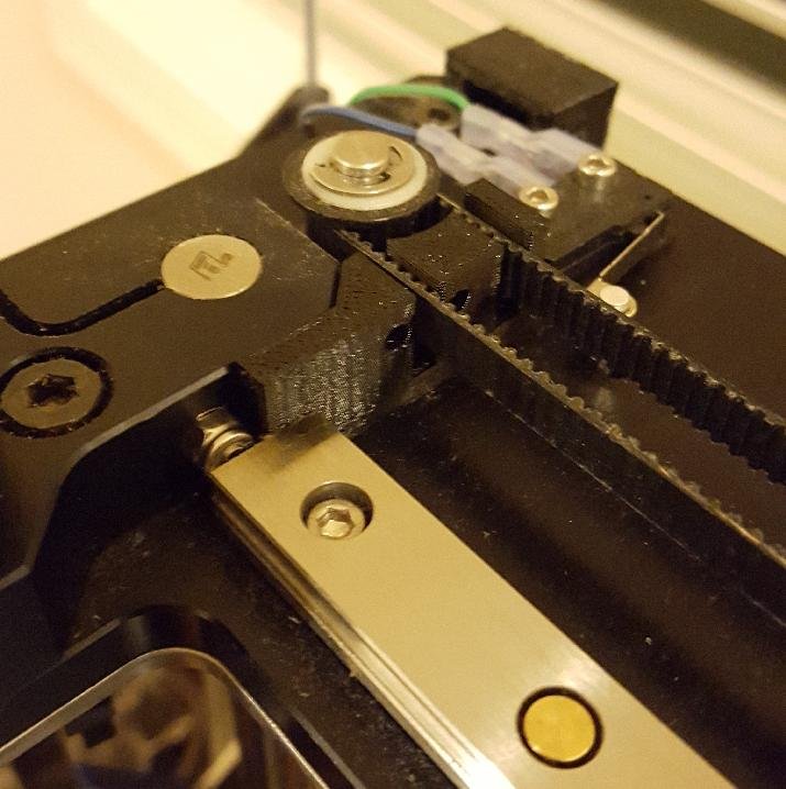
The left parking block installed (shown without magnets)You will need to unscrew the nylon spacer that blocks the end of the X rail to get the left parking block into place. The nylon spacer will then hold the parking block down, along with the back left X stepper motor screw. It should look like the photo below.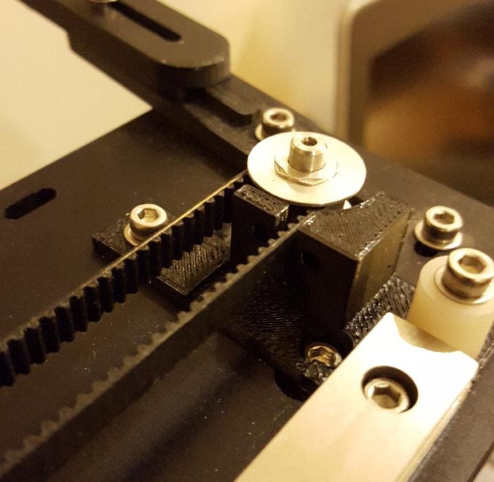
The right parking block installed (shown without magnets)While you have the nylon spacer disassembled from the end of the X rail, it would be a good time to install the second carriage. Please note that as soon as you put the second carriage on, the left extruder will no longer be able to move past the right edge of the heated bed plate, which prohibits the standard start-up sequence of moving to the right past the bed, purging, and doing a slow wipe onto the bed from the right. With the second carriage installed, the left extruder will forever after need to purge on the left side and do the slow wipe toward the right, wiping itself off on the left side of the heated bed plate.Be very, very sure that you never let the carriage leave the rail. It is full of ball bearings, and if you don't lose half of them, it will be next to impossible to get them back in. Carriages sold separately usually come bound to a plastic rail of the same dimension as the steel linear rail. Carefully unclip whatever bonds or clips are keeping the carriage on its plastic rail. Place the plastic rail against the metal rail, exactly aligned, and slide the carriage off of the plastic rail and onto the metal rail. I found that it did not slide easily across the gap, but with a little force, the carriage made it across without mishap.
Make sure that the nylon spacer is reattached and properly blocks the end of the X rail.
Step 5.
Assemble the filament drives using the same hardware as the originals. If you purchased the v4 upgrade kit, that just means removing the parts from the filament drive that came with the kit and assembling them back on the new, reversed filament drive. If you are building the filament drive from scratch, you need to order the shoulder screw and bearing (see the parts list), and add an M4 machine screw and nut as the tensioner.Likewise, the reverse-printed motor mount takes the same hardware as the original. If printing from scratch, you need the M4 x 35mm machine screws and M4 nylocks to clamp the motor mount firmly to the motor.
Remove the mount couplings from the mount plates (that were connected in step 3 to aid in aligning the magnets properly). Reconnect them with the X axis belt running through the slot. Attach the motor mount and mount plate to the rail carriage using the same hardware (M3 x 16mm) as the original.
NOTE: The dual extruder instructions call for a slip of paper between the rail carriage and the mount plate. I had no idea what this was for until I tried to bolt the mount plate directly to the rail carriage and found that the rail carriage would refuse to slide easily toward the end of the rail. So I added a piece of cardstock paper between the rail carriage and mount plate. Indeed, that solves the problem, and is presumably why the piece of paper is there in the dual extruder instructions.
Now slip the stepper motor through the motor mount and secure the clamp. Secure the filament drive directly to the motor through the top right and bottom left holes with M3 x 25mm machine screws and washers.
Motor assembly (viewed from front):
- A: Filament drive: Model STL file printed in reverse
- B: Motor mount: Model STL file printed in reverse
- C: Stepper motor
Do this assembly for both the left and right extruders, then check to make sure that both are moving freely along the rail, and that the right extruder magnetically attaches (lightly) to the right parking block, and that the left extruder attaches (lightly) to the left parking block.
Step 6.
Attach the belt clamp simply by sliding onto the belt from underneath. It does not need to be physically restrained; it will not fall off of the belt.Test that each of the left and right extruder assemblies will magnetically connect and decouple from the belt clamp, and that the belt is not chafing against any of the printed parts. If you have not tightened up the X axis belt, this is a good time to do so.
Step 7.
This is a good time to go ahead and insert the hot-ends into the brackets, letting the wires run up the right side of the filament drive. It's fine to cable-tie the heater and thermistor wires together, but it's better not to tie down those wires to anything else, so that it becomes very easy to swap out the hot-end for another one.
Step 8.
Before connecting the extruder fans, make sure that the connectors for all four fans will be compatible both on the fan side and on the wire harness side. Each wire harness has five sets of wires: (1) a two-wire thermistor connection, (2) a two-wire heater connection, (3 and 4) two two-wire fan connections, and (5) the 4-wire stepper motor connection (which goes to a six-pin connector). The newer MakerGear wire harnesses have Molex 2-pin connectors with a latch on the side for the fan.The extruder fans connect as in the MakerGear instructions for the v4 single, except in mirror image. The 12V extruder fan (if you chose to use a 12V fan, which is the traditional extruder fan type) connects by a single M3 x 40 screw that passes through the bottom right hole on the extruder. It works best if the wires of the fan come out on the same corner as the machine screw.
As noted in the printed parts list, there are many alternative designs to the fan bracket available. If you use the standard fan bracket, connect it to the left bottom side of the extruder fan using an M3 x 16 with washer and M3 nylock. One 12V extruder fan needs to be mounted on each extruder assembly.
The 24V bed fan, also one on each extruder assembly, is preferably also a 40mm x 40mm fan (see the hardware parts list) due to the short space between the two extruder assemblies. The right side can potentially take a 50mm x 50mm fan, since there's nothing on the right side of the machine to get in the way. On the left side, the fan must clear the frame and the large clamp that holds the Z-axis rods. I chose to mount the fan on the standard bracket, but with a 6mm nylon spacer (some leftover part from the M2 kit) placing it a ways forward and above, enough to clear the clamp when the left side extruder assembly is pushed all the way to its parking position on the left. Using the 6mm spacer, the fan mounts to the bracket with an M3 x 18mm machine screw and nylock. It works best if the wire comes out on the top right side.
Step 9.
If you have had the dual extruders, then the wiring harnesses have been all cross-coupled and need to be separated back into two separate harnesses all the way back to at least the point where they travel down the side of the frame; they may be tied together here and both tied to the frame (hint: Look for my wire harness guide on Thingiverse; it keeps the two cable harnesses directly behind the side of the frame so that they don't interfere with either the heated bed or with the second filament spool on the right side).Assuming that you have put the right connectors on all the fans, you can now plug everything in. All the connectors are uniquely keyed, with the fan connectors having the latch on the side, and the thermistor connector being the reverse of the heater connector so that they cannot be plugged in wrong.
For "wire management", keep everything tidied up with cable ties. Wires on the right extruder can take up as much room as they want to on the right side; there's nothing there to interfere. You will need to be more careful with the left side wiring. It cannot go on the left or it will interfere with the left side of the frame and the Z-knob. It cannot stick out too far to the right or it will prevent the back-and-forth series of movements from working properly. Try to bring the wires up as close to the right side of the filament drive as possible, and if they need to be bunched up, do it above the motor mount. After the wiring has been tied down, make sure that the left extruder can still move all the way to the left, and that the left and right extruders can touch motor mount to motor mount with no wires interfering.
Step 10.
The wiring in the electronics box (a.k.a. RAMBo) follows the wiring instructions for the MakerGear dual extruder with two exceptions: First, the left side extruder motor connector (E0) must be reversed from its original position, since the filament drive has been reversed. The second extruder motor connector (E1) will have the same orientation. You can always check this in pronterface or Simplify3D by manually extruding and retracting, and noting whether the extruder motor is turning the right direction. If not, turn the connector around on the RAMBo.Second, the 24V bed fans need to be tied together, largely due to the lack of individual outputs and controls on the RAMBo. Just make sure you know which connectors are the 24V ones and which are the 12V ones. Because the electronics enclosure fan is 12V, you have various options here, such as buying a bunch of 24V fans and making everything 24V, which is certainly the simplest solution (although also probably the noisiest solution). You could keep the two extruder fans at 12V and wire them in series, then replace the electronics enclosure fan with a 24V fan. My solution was to purchase a few 12V regulators, a simple small assembled board with a handful of components called a "buck converter". I used a single 12V buck converter to connect all three 12V fans, and the buck converter input is tied to the same RAMBo output previously connected to the extruder and case fans. The 24V bed fans are tied together (in parallel) and connected to the same bed fan output as before.
And good luck with wire management inside the electronics enclosure.
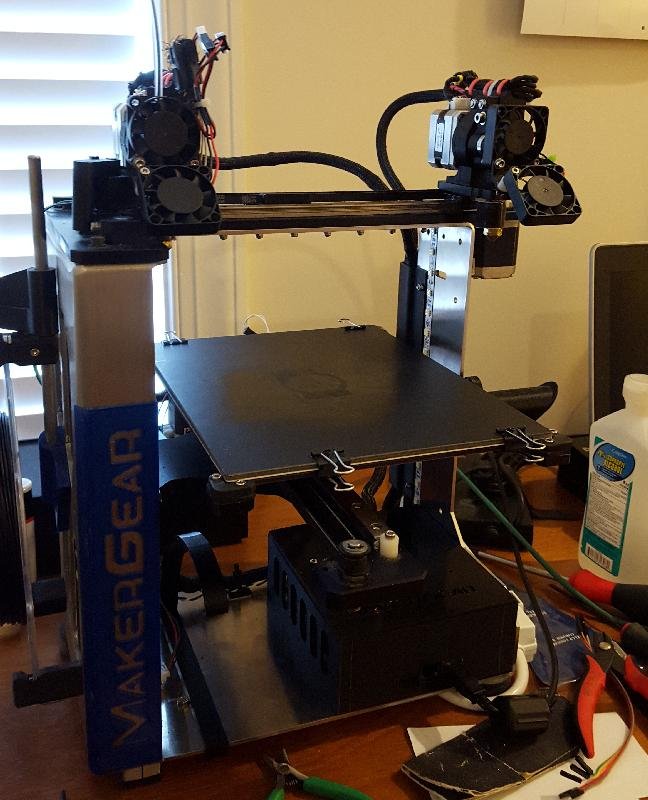
The project with both extruders mounted.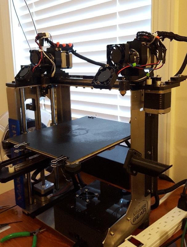
Another view of the project at this stage.
Step 11.
The point of the parking plates is to have a place for each extruder to have its nozzle rest when it is idle. To keep the nozzle from oozing, the plate should block the nozzle opening; and since the nozzle is extremely hot, that plate should be metal and be able to sink away heat pretty fast.The parking plate brackets I designed can probably use another round or two of design improvements. They are designed to take a piece of scrap plate metal (I used a piece of brass that I had lying around) that is about 13mm x 30mm x 0.4mm thick for each plate. I trimmed each one to shape with shears and fit it into the slot.
If you got the MakerGear dual extruder upgrade, it came with a little strip of pink silicone rubber. I cut this in half to make two wipers, and the right side bracket has a slot to hold it.
The right side bracket mounts to the frame and should be adjusted with the right extruder parked until the nozzle is just touching the plate.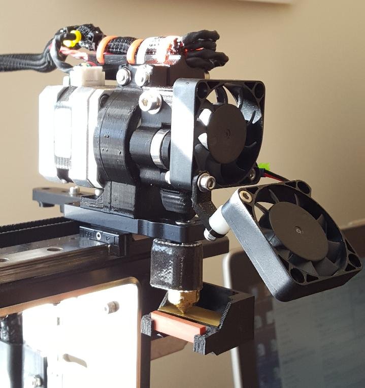
The completed right extruder assembly, showing the parking plate and wiper.The left side bracket mounts underneath the top of the frame on the left side, held in by the nuts and washers that hold the big clamp. It is the least well designed of all the parts; it is not vertically adjustible, and it does not have a place to put a wiper strip due to lack of space. This will need to be redesigned, probably to clamp around the Z-axis rod like the Z-endstop switch so that it can be adjusted up and down as needed. There is enough space for the wiper, but it needs to be carefully designed. For now, install the assembly under the frame, and adjust height by bending the plate up or down slightly as needed.
Step 12.
Almost done! Just a few bits and pieces of hardware left. If you didn't already have the dual extruder, then now is the time to connect the right side spool holder and the right side filament guide (see the MakerGear dual upgrade instructions if necessary). The plastic or teflon filament guide tubing sticks into the filament guide, and since the filament drive (in this version, at least) doesn't have a hole for the filament guide tube, you'll have to extrude some filament into the drive before it's going to stay put.There, everything is mounted, wired up, and ready to go. Hopefully it looks something like the picture below.
The completed project.
The main issue with software is getting the right starting script and getting the right tool change script. However, these are really the only two things that are needed to make the twin extruder work. But each script is lengthy and complicated. A good way to validate the operation of the script is to send each line from the script manually as a command to the printer, and watch everything in slow motion. Preferably do this with the heat off, and don't send any of the extruder motor commands (any "G1" command followed by "E" and a distance measure). Just watch the extruder movement and make sure the sequence of motions matches the description in the "How it works" section above.
After a few days of attempts to prove that the architecture will overcome the need for an ooze shield, I have more or less given up on that. I can say, however, that printing the example 8-sided die (see below) in PETg (which is drippy) using the origingal MakerGear dual extruder required me to babysit the print for the entire duration, because the part is small and the bits of oozing filament wiping off on the ooze shield kept accumulating until the birds-nest of excess filament threatened to knock down the shield. So I spent a lot of time picking excess filament from the nozzles with a pair of tweezers. Running the twin extruder project on the same print sample with the ooze shield, I was able to divert my attention elsewhere for the duration of the print, and come back to find the finished print with almost no drippings. In fact, the main use of the ooze shield ended up being to re-prime each extruder, as it appears that for each extruder, it requires some time to get started on every single layer. Attempts to compensate only using retraction and extrusion during tool changes just wasn't as effective as the ooze shield.
This startup script is not necessarily optimal, but it does the job.Note that the start script ends with T1 (right extruder) active due to a quirk (bug?) of Simplify3D, in which it always does a 1mm retraction following the start script, and then follows that with a T0-to-T0 "tool change". Switching to T1 at the end of the start script ensures that the right extruder retracts appropriately so that it can extrude again by that amount on the first tool change from T0 to T1.T0 G28 ; home all axes G1 Y20 Z1 F2500 ; drop bed slightly, clear clips T1 ; use right extruder coordinates G1 X200 F9600 ; move right G1 X230 Y40 F3000 ; grab right G1 X225 Z10 F3000 ; move to purge point G1 Z0.4 ; position nozzle G92 E0 ; zero extruder G1 E15 F225 ; purge nozzle G92 E0 ; zero extruder G1 X200 Z0.1 F1200 ; slow wipe G1 X190 Y50 Z1 ; lift T0; switch to left extruder coordinates G1 X30 F9000 ; back to left G1 X-3 F3000 ; grab left extruder G1 X150 F9000 ; park right extruder T1 G1 X203 F3000 ; slower move to park T0 G1 X0 F9000 ; back to home position G1 Z0 ; bring bed back to position G1 Y50 Z0.3 F9600 ; move forward to avoid binder clips G1 X2 Z10 ; move to purge point (2mm) G1 Z0.4 ; position nozzle G92 E0 ; zero extruder G1 E15 F225 ; purge nozzle G92 E0 ; zero extruder G1 X20 Z0.1 F1200 ; slow wipe (to 20mm) G1 X30 Z0.25 ; lift T1
The tool change script makes use of "[old_tool]" and "[new_tool]" substitutions, but also makes use of Simplify3D's "IF" statement blocks, which make it an awkward equivalent to having individual scripts for changing left-to-right or right-to-left.T[old_tool] G91 ; relative mode G1 Z1 ; drop bed for tool change G90 ; absolute mode G1 E-1 ; retract T[new_tool] {IF NEWTOOL=1}G1 X200 F9600 ; latch right {IF NEWTOOL=1}G1 X230 F3000 ; slow latch {IF NEWTOOL=1}G1 X200 F3000 ; slow pull away {IF NEWTOOL=0}G1 X30 F9000 ; latch left {IF NEWTOOL=0}G1 X-3 F3000 ; slow latch {IF NEWTOOL=0}G1 X30 F3000 ; slow pull away {IF NEWTOOL=1}T0 {IF NEWTOOL=0}T1 {IF NEWTOOL=1}G1 X50 F9000 {IF NEWTOOL=1}G1 X24 F3000 ; park left {IF NEWTOOL=0}G1 X170 F9000 ; park right {IF NEWTOOL=0}G1 X203 F3000 ; slow park T[new_tool] G92 E0 G1 E1 ; extrude G92 E0 G91 ; relative mode G1 Z-1 ; raise bed back to position G90 ; absolute mode
Below are the filament process files for the twin extruder project, and a complete factory file containing the processes and the "die8_color" two-color sample model.I have also included process profiles for each extruder separately, allowing one to print with only the left or only the right extruder. The left-only profile assumes that the right extruder is parked throughout the print; it does not attempt to have the left extruder force the right one into the parking position. Naturally, the single-extruder configurations do not include tool changes.
Currently only PETg profiles are available, but the main thing to get from the profiles is the start script and tool change scripts.
File Type Revision Size Date PETg_new_dual_left.fff S3D filament profile 0 12.0kB December 15, 2015 PETg_new_dual_right.fff S3D filament profile 0 12.1kB December 15, 2015 PETg_new_single_left.fff S3D filament profile 0 10.8kB December 17, 2015 PETg_new_single_right.fff S3D filament profile 0 10.9kB December 17, 2015 die8_color.factory S3D factory file 0 176.0kB December 15, 2015
The slic3r scripts are very similar to the Simplify3D scripts, with a few minor variations. For example, this one doesn't end with a switch to T1, because there's no extraneous retraction after startup that can't be removed.T0 G28 ; home all axes G1 Y20 Z1 F2500 ; drop bed slightly, clear clips T1 ; use right extruder coordinates G1 X200 F9600 ; move right G1 X230 Y40 F3000 ; grab right G1 X225 Z10 F3000 ; move to purge point G1 Z0.4 ; position nozzle G92 E0 ; zero extruder G1 E15 F225 ; purge nozzle G92 E0 ; zero extruder G1 X200 Z0.1 F1200 ; slow wipe G1 X190 Y50 Z1 ; lift T0; switch to left extruder coordinates G1 X30 F9000 ; back to left G1 X-3 F3000 ; grab left extruder G1 X150 F9000 ; park right extruder T1 G1 X203 E-1 F3000 ; slower move to park, and retract G92 E0 T0 G1 X0 F9000 ; back to home position G1 Z0 ; bring bed back to position G1 Y50 Z0.3 F9600 ; move forward to avoid binder clips G1 X2 Z10 ; move to purge point (2mm) G1 Z0.4 ; position nozzle G92 E0 ; zero extruder G1 E15 F225 ; purge nozzle G92 E0 ; zero extruder G1 X20 Z0.1 F1200 ; slow wipe (to 20mm) G1 X30 Z0.25 ; lift ; end of custom G-code
Again, this is very much like the Simplify3D tool change script, except it does not do an initial switch to the old tool, and the IF statements have been replaced with a method that works with (and only with) the post-processing script (see below).G91 ; relative mode G1 Z1 ; drop bed for tool change G90 ; absolute mode G1 E-1 ; retract G92 E0 T[next_extruder] {[next_extruder]=1}G1 X200 F9600 ; latch right {[next_extruder]=1}G1 X230 F3000 ; slow latch {[next_extruder]=1}G1 X200 F3000 ; slow pull away {[next_extruder]=0}G1 X30 F9000 ; latch left T[previous_extruder] {[next_extruder]=1}G1 X50 F9000 {[next_extruder]=1}G1 X24 F3000 ; park left {[next_extruder]=0}G1 X170 F9000 ; park right {[next_extruder]=0}G1 X203 F3000 ; slow park T[next_extruder] G92 E0 G1 E1 ; extrude G92 E0 G91 ; relative mode G1 Z-1 ; raise bed back to position G90 ; absolute mode
Below are setup files for use with slic3r. The post-processing file handles the asymmetric tool changes in a similar way to Simplify3D's {IF} statements. But it also handles the incorrect skirt generation, in a way that should be robust to how the skirt is set up.The slic3r initialization file contains the start script and toolchange script with syntax designed for the post-processing script. It is necessary to go to "Print settings" and click on "Output options", and change the path to the post-processing script as necessary.
The file has not been very well optimized; the tool speeds should be adjusting for print size but are not, which causes this setup file to make the printer run too fast for the sample file. Updates will be made as I work out these issues.
The post-processing script has been written for Linux systems in its attempt to write the temporary output into the "/tmp" directory, and to make system calls to Unix copy and remove file commands. This is fairly easy to change for Windows or Mac systems with a quick check of the OS type, but at the moment the script is only supporting Linux systems. If anybody gets this far with the project and is working in a Windows or Mac enviroment, and neither slic3r or Simplify3D has been updated with a correction in response to my pleas, then let me know and I can update the script.
File Type Revision Size Date M2twin_PETg.ini Slic3r init file 0 5.6kB December 14, 2015 twin_postproc.tcl Tcl script 1 5.7kB December 14, 2015
Note: Setting up the dual extrusion with an ooze shield is recommended, and that can be done in a way that doesn't require special handling of the skirt. Specifically, one should set up the ooze shield to be printed by both extruders (since one of its purposes is to prime each nozzle at the start of every layer), and print the skirt with the left extruder only, using 3 or more perimeters of skirt to help hold the ooze shield down. The ooze shield itself need not be more than one perimeter thick. Put the skirt at 0 mm distance from the object; this will cause the skirt to be attached to the ooze shield. The first layer of the ooze shield will be printed with the right extruder, so that the right extruder is properly primed.Read the comments below only for attempting to print without an ooze shield. Since I have not found a way to print that works so well as to not require an ooze shield, these instructions may not be necessary.
Neither of the slicers I use does dual extrusion skirts right. I have complained to Simplify3D support, and maybe one day they will come around to realizing the error of their ways and fix it. I have complained to the Slic3r development team, and am waiting for an answer. In the meantime, I am working on a post-processing script to circumvent the slicer stupidity and generate the right gcode. See the "testing" section below for a hand-modified file that has what the post-processing script is supposed to produce.
In short, there are two separate errors in the slicer output. The first is that the skirts are generated in a back-and-forth sequence of left, right, left, right, wasting a lot of time and priming each extruder multiple times, which they don't need. The second error, which is the worse one, is that the sequence of skirt and model first layer printing is done in the order: left skirt, right skirt, left first layer, right first layer. This undermines the whole concept of using the skirt to prime the extruders, since in this order, each extruder goes idle immediately after priming, and is therefore un-primed by the time it starts working on the model. The proper order should be: left skirt, left first layer, right skirt, right first layer.
The post-processing script can fix this as long as the output gcode settings are set to "verbose", so that the output clearly defines which instructions comprise the skirt and which instructions comprise the model. Then the alternating skirt outlines can be combined into one set of outlines for each of left and right extruders, and the right extruder skirt outlines moved down in the code to happen after the left extruder has finished printing the first model layer.
By design, this project does not require custom firmware changes. The only firmware modifications are to make sure that you have the dual extruder enabled firmware; this can be obtained from the MakerGear Dual extruder instructions page. Follow the instructions for firmware updates there.Within the firmware configuration, it is necessary to set the offsets of the 2nd extruder relative to the 1st. See the same page for the MakerGear dual instructions (above), and go to the section at the bottom labeled "Tool offsets" and follow the instructions there. By default, the dual firmware uses an offset appropriate for the MakerGear dual extruder, which is 31.1mm. For the twin extruder project, the offset is not nearly as reliable a number. Start with an X offset of 20.6mm and a Y offset of 0.0mm, and expect to modify either one or both up to a few millimeters as necessary to achieve proper calibration.
The main point of calibration is to find the X and Y offsets between the two nozzles. Use the calibration objects and the calibration procedure outlined in the instructions for the MakerGear dual upgrade kit. Because the MakerGear dual has the two extruders aligned by holes drilled into the same mount plate by precision machinery, calibration is largely a formality. Plug in 31.1mm for the X offset and 0.0mm for the Y offset and there is very little likelihood of needing to change it. Not so for the twin extruder. The mount plates have a bit of slop in the diameter of the holes for the M3 screws holding them to the rail carriage, so the two mount plates can differ in position by up to a millimeter or two in both the X and Y directions. The nominal distance between the two extruders is something like 20mm in X and 0mm in Y, so these are good values to plug in to start with. It will require several calibration runs to find the exact values needed. But those values should remain good as long as you don't disassemble either mount plate. Any time either mount plate (or motor mount, since it holds the mount plate to the rail carriage) is loosened or removed from the carriage rail, calibration will have to be re-done. Fortunately, it is very rare to need to do this.
The sample model is from my set of two-color dice on Thingiverse.The print "die8_color.g" was generated with Simplify3D and includes an ooze shield. This setup is close to optimal but probably needs some tweaking on the retraction during tool changes.The print "die8_color_noshield.g" was generated with slic3r and has been post-processed automatically with the script above to correct the way the skirt is drawn. Speeds are too high for the size of the part, and need to be turned down more. I will post an update once I get around to correcting the slic3r setup.
File Type Revision Size Date die8_color_noshield.g g-code 1 1.0MB December 14, 2015 die8_color.g g-code 1 1.2MB December 15, 2015 
g-code preview of the die8_color_noshield.g file. Lines going off to the right and left are the tool change movements.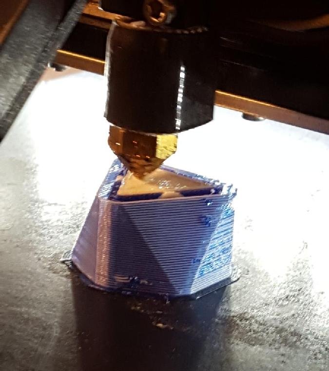
Printing the die8_color sample, with ooze shield. Note that the ooze shield is relatively clean, but is catching a few stray drips of blue PETg.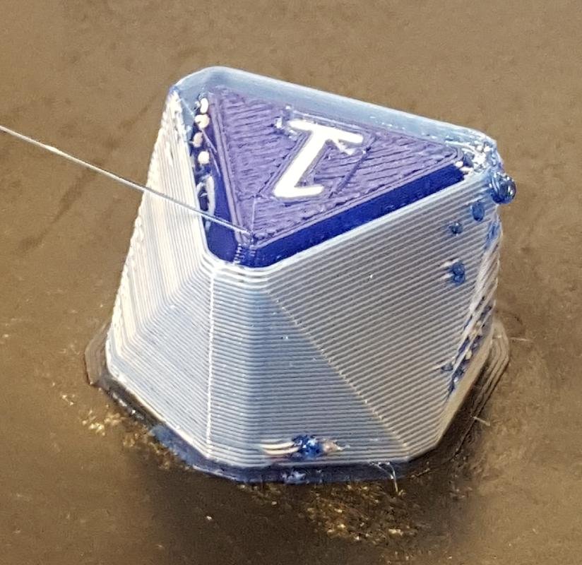
The finished die8_color print. Some of the white PETg has managed to get over the ooze shield; still looking into how to prevent that.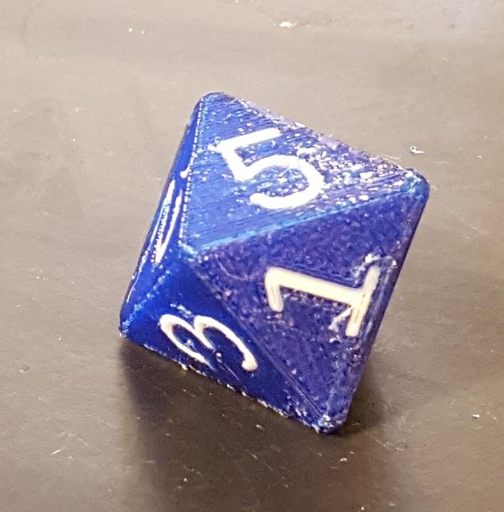
In the end, the model printed relatively well except for some of the stray bits of white PETg that escaped over the ooze shield and got embedded into the surface.Although the sample print did not have the resistance to drips and oozes that I was hoping for, it does validate the basic underlying premise of the project that the magnetic coupling does not in any way degrade the quality of a print, and that it is possible and even practical to run two single-ended extruders with independent motion on a single belt drive.
Testing the Twin Extruder (1)
MakerGear M2 custom twin extruder test (December 7, 2015)
Testing the Twin Extruder (2)
MakerGear M2 customized twin extruder test (December 8, 2015)
Twin Extruder Epic Fail
Twin extruder epic fail (December 7, 2015)
This is what happens when the printer nozzle isn't secured to the mount plate. The nozzle was a tight fit, and the screws were tight, and I didn't realize that they weren't tapped into the other side of the clamp. When the mount plate heated up, the clamp expanded, the nozzle dropped out, and plowed into the print, not only destroying the print but also damaging the surface of the Zebra plate underneath.
Here are some ideas for near-term projects and other ideas which I may or may not pursue with the twin extruder project.Improved left parking
Left side parking needs to mount the other silicone rubber wiper. My original idea called for a space between the parking plate and the wiper, where the nozzle could be purged. In retrospect, I don't think the nozzle needs to be purged behind the wiper; at the beginning of the print, it wipes just fine on the heated bed plate. So the wiper can be positioned directly in front of the plate, which should give it enough room to clear the heated bed's corner brackets.Additionally, the current left side parking suffers from a lack of adjustment capability. It should work like the right side, in which it can be moved up and down slightly until it can be aligned properly so that the nozzle just touches the plate in the parking position. To do that on the left side probably requires that the parking plate assembly be mounted by clamp to the Z-axis rod like the Z-endstop switch is, instead of being mounted under the frame. Or a 2-part bracket would work as well.
Z-endstop switch reference to heated bed surface
MakerGear has recently been experimenting with putting the Z endstop switch on the bottom of the machine so that it can be referenced to the bed plate itself, rather than the original position, where it is engaged by the base of the Z stage assembly. That way, any change to the bed leveling also changes the relationship between the Z stage base and the bed surface, so the Z endstop position has to be re-calibrated.With the original architecture, the bed surface cannot engage the Z switch, because that implies that the Z switch has to be lower than the extruder nozzles, where it would have to be moved prior to printing or else get in the way of the print. The twin extruder architecture allows this configuration, however, because in the parked position, both extruders are off of the bed, and the bed can be moved higher than the nozzle position.
But while a Z endstop switch mounted under the top of the frame gives the proper reference to the bed surface, it is critically important that both nozzles be parked whenever the Z axis is homed. If not, the bed crashes into the nozzles, and that, of course, is very bad. In the end, it is probably better to develop the Z-probe mount (see below) and use the Z-probe as the endstop switch.
Z-probe mount (Completed December 23, 2015)
I used to have a Z-probe mount on my MakerGear dual extruder, which I carefully designed to mount right through the middle of the fan duct, and which worked very well. It had only one serious drawback, which was that it had to be mounted forward of the nozzles, and that meant that when the extruder went to the home Y position, the Z-probe was sitting over air in front of the heated bed. So the probing method had to be carefully arranged to make sure that it never tried to home the Z axis while the Y axis was at zero. In the end, I kept the Z end-stop switch as the main reference, which worked reasonably well, except that the arrangement fails to get over one of the original problems being solved by the Z-probe, which is that the Z end-stop switch references the base of the Z-stage assembly, and not the heated bed plate surface.But with the twin extruder, it is actually possible to mount the Z-probe much like it is mounted on the single V4 extruder, with the probe to the side of or slightly behind the nozzle, where it overcomes the problem mentioned above; it never goes off of the edge of the heated bed plate. But the mount needs to be very carefully designed so that it does not add extra space between the extruders. Note that this is not a requirement, but anything that increases space between the two extruders limits the maximum range of the left extruder, so it cuts down on the maximum print volume.
The STL download below is a modified single v4 filament drive with a bracket that holds an inductive Z-probe type LJ12A3-4-Z/BY. The bracket is positioned so that the Z-probe can sit with the tip a few millimeters higher than the nozzle, and be clamped to the bracket with nuts on top and bottom. Amazingly, the Z-probe nestles in between the two extruders without increasing the distance between them.
File Type Revision Size Date left_drive_zprobe.stl STL 0 3.26MB December 23, 2015 left_drive_zprobe.scad openSCAD 0 3.0kB December 23, 2015 Note that this filament drive is copied from the original MakerGear model (it also has the added socket for the filament guide tube, like the one in the "Original STL files" list above), so it needs to be printed in reverse like the other filament guides. The new filament drive with the bracket replaces the one on the left extruder, with the bracket to the right of the nozzle, so that the Z-probe sits between the two extruders (but attached to the left one).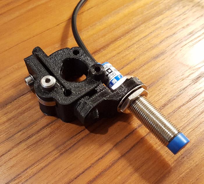
Left filament drive with bracket for an inductive Z-probeYou will want to insert the Z-probe from the bottom, threading the Z-probe wires through the hole in the bracket first, then adding the nut on top, and finally adding the nut on the bottom.
This report only describes how to mount the Z-probe, not how to electrically connect it or use it.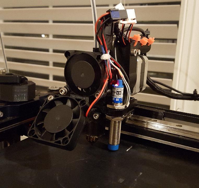
Completed extruder assembly with inductive Z-probe
Increased X axis range
Although the effective distance between the two extruders is less than the distance between the extruders in the MakerGear dual extruder, the range of the left extruder along the X axis gets limited by the right extruder being in the way. On the MakerGear dual, the motors are cleverly mounted with nearly zero space in between. Also, the right motor extends out to the right of the rail carriage, so it can actually travel past the end of the rail. That allows the left extruder to keep its original full X axis range.The twin extruder architecture is limited by the need to have two rail carriages. In the current version, the left extruder loses a full 2cm of range on the right side. A small amount of this could be recovered by some redesign of the motor mount. But only about a half-centimeter could be recovered, so it may not be worth the effort.
With the addition of the Z-probe (see above), there is even less space to recover, so it is is unlikely that this idea will ever be realized.
There is, however, one optimization that does recover some X-axis range, and that is to use the newer metal motor mounts. The metal mounts were only just introduced by MakerGear about the time that I started on this project, and it was just one additional complication I did not want to get into. The one problem with the metal mounts is that to recover the space, one of them needs to be mounted backwards. It turns out that there is no problem with the mount fitting in that orientation, but the screw holes need to be re-drilled. The use of the metal brackets recovers about 1 to 2 cm of travel for both extruders, plus the bracket is just overall better than the printed version.
Simultaneous ("ditto") printing
A fairly straightforward firmware change can copy all of the left extruder commands to the right extruder. If the two extruders are then tied together with a linkage at a set distance, two models can be printed at the same time, doubling the print capacity of the printer.Unfortunately, most (all?) firmwares are set up to define a "current extruder", and most G-code follows the practice of setting the "current tool" with T0 and T1, and then specifying the extruder movement with "G1 E", where "E" then is interpeted in the context of the current tool. It's a totally unnecessary contrivance that derives from the origins of G-code for milling tools and such, but prevents certain obvious optimizations of dual-extruder setups like retracting one extruder and advancing the other at the same time, or just running both in concert as suggested here.
On the other hand, given that a "ditto printing" setup requires a hardware linkage, one could also simply require a wire Y-connector to both extruder stepper motor drives. Add the linkage, add the Y-connector, and it's all done, no firmware changes required.
Quick and easy solution for the linkage: Print a second magnetic belt clamp. Place it on the belt to the right of the first belt clamp. Couple the right extruder to it. Distance is adjustible in units of the belt clamp spacing of ridges, which is 2mm.
Below are links to a secondary belt clamp that can be placed to the right of the primary belt clamp. It lacks the extension to trip the X-axis minimum endstop, so it should only be used as the secondary belt clamp. Make sure the magnets are installed in the same direction as on the original belt clamp. The position of this clamp on the belt determines the distance between the two extruders. It is up to the end-user to ensure that a print does not cause the right extruder to exceed the maximum reachable X dimension.
The Marlin-X2 firmware code allows a single command to be passed to more than one extruder, in some cases with different parameters passed to each. Sailfish has an option for ditto printing. As of this writing, neither the stock Marlin firmware nor Smoothieware support ditto printing. I have created a fork of Smoothie to support the twin extruder project. The fork can be found on github at RTimothyEdwards/Smoothieware. The git branch is "feature/ditto-printing" (i.e., "git checkout feature/ditto-printing"). I started a forum thread on it at Ditto printing for Smoothieware. As it says in the post, questions, comments, and suggestions are welcome.
File Type Revision Size Date belt_clamp_secondary.stl STL 0 2.04MB December 24, 2015 belt_clamp_secondary.scad openSCAD 0 1.5kB December 24, 2015 With the Smoothieware modification, the RepRap G-code command "M605 S2" puts the printer into "ditto mode", with the second extruder receiving a copy of all stepper commands that are passed to the first extruder. All X axis movements, however, will be made relative to the first extruder. The command "M605 S0" returns the firmware to standard mode, with the extruders operating independently. Standard mode is the default. Note that the M605 command is defined relative to the "active extruder" at the time the command is processed, so by sending command "T1" first, the command will copy from the second extruder to the first. This independence of the ditto mode from the tool change commands allows the extruders to be run at different temperatures (although, in general, it is strongly recommended for ditto printing that both sides be as closely matched in setup as possible: same size nozzle, same filament, same temperature).
Below is a video of the twin extruder printing in ditto mode. The major difficulty with ditto mode is the problem of purging and wiping both sides. Although not shown in the video, for this first test print, I purged both nozzles at the same time, with the right extruder decoupled from the magnet and held over the right edge of the plate. During the slow wipe on the left side, the right extruder was manually moved over to couple to the belt clamp. The process can be done through the start script, but the extruders will have to purge individually before setting ditto print mode, with the additional complication of having to know the offset of the right extruder to make sure that it is placed correctly for purging.
Twin extruder ditto print! (January 11, 2016)
This video shows the M2 twin extruder in ditto printing mode, which requires some firmware source code modifications but otherwise is a simple extention of the twin extruder project. A "Ditto printer" uses two or more extruders separated by a distance along the X axis, but responding equally to X axis movement and extrusion/retraction commands, to print multiple copies of the same print at the same time. In the "twin extruder" setup, a second magnetic belt grip is placed to the right of the main magnetic belt grip, and the right extruder couples to it. Since the belt grip is just slipped over the belt, the distance between the extruders for ditto printing can be adjusted quickly and easily.
![]()
| email: | 
|
Last updated: December 20, 2015 at 10:43am