
Tutorials to read first:
Magic Tutorial #1: Getting Started
Magic Tutorial #2: Basic Painting and Selection
Commands introduced in this tutorial:
array, corner, fill, flush, plow, polygon, straighten, tool, wire
Macros introduced in this tutorial:
<
>
Tutorial #2 showed you the basic facilities for placing paint and labels, selecting, and manipulating the things that are selected. This tutorial describes two additional facilities for manipulating paint: wiring and plowing. These commands aren't absolutely necessary, since you can achieve the same effect with the simpler commands of Tutorial #2; however, wiring and plowing allow you to perform certain kinds of manipulations much more quickly than you could otherwise. Wiring is described in Section 2; it allows you to place wires by pointing at the ends of legs rather than by positioning the box, and also provides for convenient contact placement. Plowing is the subject of Section 3. It allows you to re-arrange pieces of your circuit without having to worry about design-rule violations being created: plowing automatically moves things out of the way to avoid trouble.
The box-and-painting paradigm described in Tutorial #2 is sufficient to create any possible layout, but it's relatively inefficient since three keystrokes are required to paint each new area: two button clicks to position the box and one more to paint the material. This section describes a different painting mechanism based on wires. At any given time, there is a current wiring material and wire thickness. With the wiring interface you can create a new area of material with a single button click: this paints a straight-line segment of the current material and width between the end of the previous wire segment and the cursor location. Each additional button click adds an additional segment. The wiring interface also makes it easy for you to place contacts.
tool info
This command prints out the name of the current tool and the meaning of the buttons. Run Magic on the cell tut3a and type tool info. The Tcl/Tk-enabled version of Magic uses Tcl scripts to implement the tools. You will get a slightly different output with the "info" option than for the non-Tcl/Tk-enabled version.
The tool command can also be used to switch tools. Try this out by typing the command
tool
Magic will print out a message telling you that you're using the
"wiring tool", and the cursor will change to an arrow
 shape. Use
the tool info command
to see what the buttons mean now. You'll be using the wiring tool
for most of the rest of this section. The macro " " (space)
corresponds to tool.
Try typing the space key a few times: Magic will cycle circularly
through all of the
available tools. There are four tools in Magic version 7.4: The
"box tool", which you already know about, the "wiring tool", which
you'll learn about in this tutorial, the "netlist tool", which has a
'flower' cursor shape
shape. Use
the tool info command
to see what the buttons mean now. You'll be using the wiring tool
for most of the rest of this section. The macro " " (space)
corresponds to tool.
Try typing the space key a few times: Magic will cycle circularly
through all of the
available tools. There are four tools in Magic version 7.4: The
"box tool", which you already know about, the "wiring tool", which
you'll learn about in this tutorial, the "netlist tool", which has a
'flower' cursor shape  and is used
for netlist editing, and the "pick tool",
which has a 'circular crosshair'
and is used
for netlist editing, and the "pick tool",
which has a 'circular crosshair'  cursor
shape and was explained in
Tutorial #2. The netlist tool is explained in
detail in "Tutorial #7: Netlists and Routing".
cursor
shape and was explained in
Tutorial #2. The netlist tool is explained in
detail in "Tutorial #7: Netlists and Routing".
The current tool affects only the meanings of the mouse buttons. It does not change the meanings of the long commands or macros. This means, for example, that you can still use all the selection commands while the wiring tool is active. Switch tools to the wiring tool, point at some paint in tut3a, and type the s macro. A chunk gets selected just as it does with the box tool.
There are four basic wiring functions: selecting the wiring material,
adding a leg, changing the route width, and adding a contact. This
section describes the first three commands. At this point you should
be editing the cell tut3a with the wiring tool active. The
first step in wiring is to pick the material and width to use for wires.
This can be done in two ways. The easiest way is to find a piece
of material of the right type and width, point to it with the
cursor,
and click the left mouse button. Try this in tut3a
by pointing to the label 1 and left-clicking. Magic prints out
the material and width that it chose, selects a square of that
material and width around the cursor, places the box around
the square, and switches to the "pointing hand"  cursor. When you move the mouse, a box with a thin border (like
the selection boxes) appears, and follows the cursor in the Manhattan
direction (N, S, E or W) that puts the end of the box closest to the
position of the cursor. You can cancel the box by clicking the
right mouse button, which returns the cursor to the
shape.
cursor. When you move the mouse, a box with a thin border (like
the selection boxes) appears, and follows the cursor in the Manhattan
direction (N, S, E or W) that puts the end of the box closest to the
position of the cursor. You can cancel the box by clicking the
right mouse button, which returns the cursor to the
shape.
Try pointing to various places in tut3a and left-clicking, then right-clicking, to see how magic selects different materials and wire widths for wire routing.
Once you've selected the wiring material, the interactive box that follows the cursor shows where the next wire leg will be painted. The middle mouse button finishes the wire leg by painting the wire material inside this box. Left-click on label 1 to select the red material, then move the cursor over label 2 and click the middle mouse button. This will paint a red wire between 1 and 2. The box is placed over the tip of the new leg to show you the starting point for the next wire leg. Add more legs to the wire by clicking the left mouse button at label 3 and then at label 4. Use the mouse buttons to paint another wire in blue from label 5 to label 6 to label 7.
Each leg of a wire must be either horizontal or vertical. If you move the cursor diagonally, Magic will still paint a horizontal or vertical line (whichever results in the longest new wire leg). To see how this works, left-click on 8 in tut3a, then middle-click on 9. You'll get a horizontal leg. Now undo the new leg ("u" key) and middle-click on 10. This time you'll get a vertical leg. You can force Magic to override the selection box and paint the next leg in a particular direction with the commands
wire horizontal
wire vertical
Try out this feature by left-clicking on 8 in tut3a, moving the cursor over 10, and typing wire horiz (abbreviations work for wire command options just as they do elsewhere in Magic). This command will generate a short horizontal leg instead of a longer vertical one.
wire increment widthMice that have scroll wheels implement a simplified "wire width increment/decrement" function. Rolling the wheel upward increments the wire width, and rolling the wheel downward decrements the wire width.
wire decrement width
Note that the selection box does not change in width until the mouse is moved and the position of the box is updated, along with the width.
wire increment typebut its action depends on the proper type definitions being defined in the technology file. For example, if you draw a route using layer "nwell" and click Shift-left-button, Magic says "No routing layer defined". This means that the technology file does not define "nwell" as a routing layer, and does not define a contact type to connect between nwell and other layers (see "The Technology File Manual" for details on the technology file wiring section).
Now that you have drawn a metal 2 route to label 4, press the Shift key and, while holding it down, click the right mouse button. You will get another via (metal1-to-metal2 contact). Now continue the route to label 2. You will find that the route is drawn in metal1 (blue). The command implemented by the key-button macro "Shift + right-button" is
wire decrement typeAnd has the opposite effect of the option "increment type": it changes the wiring material type to that which is one plane below the current material type, and draws the appropriate contact type for electrically connecting the two materials.
In the examples so far, each new wire leg appeared to be drawn from the end of the previous leg to the cursor position. In fact, however, the new material was drawn from the box to the cursor position. Magic automatically repositions the box on each button click to help set things up for the next leg. Using the box as the starting point for wire legs makes it easy to start wires in places that don't already have material of the right type and width. Suppose that you want to start a new wire in the middle of an empty area. You can't left-click to get the wire started there. Instead, you can left-click some other place where there's the right material for the wire, type the space bar twice to get back the box tool, move the box where you'd like the wire to start, hit the space bar once more to get back the wiring tool, and then right-click to paint the wire. Try this out on tut3a.
When you first start wiring, you may not be able to find the right kind of material anywhere on the screen. When this happens, you can select the wiring material and width with the command
wire type layer width
Then move the box where you'd like the wire to start, switch to the wiring tool, and left-click to add legs.
Each time you paint a new wire leg or contact using the wiring commands, Magic selects the new material just as if you had placed the cursor over it and typed s. This makes it easy for you to adjust its position if you didn't get it right initially. The stretch command (Shift-Keypad key macros) is particularly useful for this. In tut3a, paint a wire leg in blue from 5 to 6 (use flush to reset the cell if you've made a lot of changes). Now type Shift-Keypad-6 two or three times to stretch the leg over to the right. Middle-click over purple material, then use Shift-Keypad-2 to stretch the contact downward.
It's often hard to position the cursor so that a wire leg comes out right the first time by "eyeballing" it. However, when the interactive crosshair is enabled, wiring becomes very easy. Turn on the interactive crosshair (Tcl/Tk-enabled Magic only) by selecting menu button Options, then click on the check button Crosshair. Try routing some wires on cell tut3a, using the crosshair for alignment. Note how much easier it is to place the route directly on the labels.
Magic provides two additional commands that are useful for running bundles of parallel wires. The commands are:
fill direction [layers]
corner direction1 direction2 [layers]
To see how they work, load the cell tut3b. The fill comand extends a whole bunch of paint in a given direction. It finds all paint touching one side of the box and extends that paint to the opposite side of the box. For example, fill left will look underneath the right edge of the box for paint, and will extend that paint to the left side of the box. The effect is just as if all the colors visible underneath that edge of the box constituted a paint brush; Magic sweeps the brush across the box in the given direction. Place the box over the label "Fill here" in tut3b and type fill left.
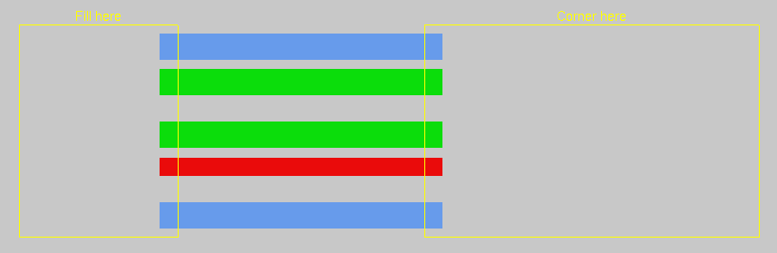
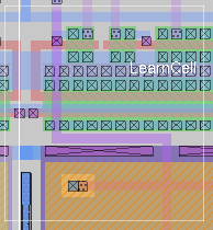
Figure 1: The initial layout of tutorial file tut3a.
The corner command is similar to fill except that it generates L-shaped wires that follow two sides of the box, traveling first in direction1 and then in direction2. Place the box over the label "Corner here" in tut3b and type corner right up.
In both fill and corner, if layers isn't specified then all layers are filled. If layers is given then only those layers are painted. Experiment on tut3b with the fill and corner commands.
When you're painting bundles of wires, it would be nice if there were a convenient way to place contacts across the whole bundle in order to switch to a different layer. There's no single command to do this, but you can place one contact by hand and then use the array command to replicate a single contact across the whole bundle. Load the cell tut3c. This contains a bundle of wires with a single contact already painted by hand on the bottom wire. Type s with the cursor over the contact, and type S with the cursor over the stub of purple wiring material next to it. Now place the box over the label "Array" and type the command array 1 10. This will copy the selected contact across the whole bundle.
The syntax of the array command is
array xsize ysize
This command makes the selection into an array of identical elements. Xsize specifies how many total instances there should be in the x-direction when the command is finished and ysize specifies how many total instances there should be in the y-direction. In the tut3c example, xsize was one, so no additional copies were created in that direction; ysize was 10, so 9 additional copies were created. The box is used to determine how far apart the elements should be: the width of the box determines the x-spacing and the height determines the y-spacing. The new material always appears above and to the right of the original copy.
In tut3c, use corner to extend the purple wires and turn them up. Then paint a contact back to blue on the leftmost wire, add a stub of blue paint above it, and use array to copy them across the top of the bundle. Finally, use fill again to extend the blue bundle farther up.
plow direction [layers]
where direction is a Manhattan direction like left and layers is an optional, comma-separated list of mask layers. The plow command treats one side of the box as if it were a plow, and shoves the plow over to the other side of the box. For example, "plow up" treats the bottom side of the box as a plow, and moves the plow to the top of the box.
As the plow moves, every edge in its path is pushed ahead of it (if layers is specified, then only edges on those layers are moved). Each edge that is pushed by the plow pushes other edges ahead of it in a way that preserves design rules, connectivity, and transistor and contact sizes. This means that material ahead of the plow gets compacted down to the minimum spacing permitted by the design rules, and material that crossed the plow's original position gets stretched behind the plow.
You can compact a cell by placing a large plow off to one side of the cell and plowing across the whole cell. You can open up space in the middle of a cell by dragging a small plow across the area where you want more space.
To try out plowing, edit the cell tut3d, place the box over the rectangle that's labelled "Plow here", and try plowing in various directions. Also, try plowing only certain layers. For example, with the box over the "Plow here" label, try
plow right metal2
Nothing happens. This is because there are no metal2 edges in the path of the plow. If instead you had typed
plow right metal1
only the metal would have been plowed to the right.
In addition to plowing with the box, you can plow the selection. The command to do this has the following syntax:
plow selection [direction [distance]]
This is very similar to the :stretch command: it picks up the selection and the box and moves both so that the lower-left corner of the box is at the cursor location. Unlike the :stretch command, though, plow selection insures that design rule correctness and connectivity are preserved.
Load the cell tut3e and use a to select the area underneath the label that says "select me". Then point with the cursor to the point labelled "point here" and type plow selection. Practice selecting things and plowing them. Like the :stretch command, there is also a longer form of plow selection. For example, plow selection down 5 will plow the selection and the box down 10 units.
Selecting a cell and plowing it is a good way to move the cell. Load tut3f and select the cell tut3e. Point to the label "point here" and plow the selection with plow selection. Notice that all connections to the cell have remained attached. The cell you select must be in the edit cell, however.
The plowing operation is implemented in a way that tries to keep your design as compact as possible. To do this, it inserts jogs in wires around the plow. In many cases, though, the additional jogs are more trouble than they're worth. To reduce the number of jogs inserted by plowing, type the command
plow nojogs
From now on, Magic will insert as few jogs as possible when plowing, even if this means moving more material. You can re-enable jog insertion with the command
plow jogs
Load the cell tut3d again and try plowing it both with and without jog insertion.
There is another way to reduce the number of jogs introduced by plowing. Instead of avoiding jogs in the first place, plowing can introduce them freely but clean them up as much as possible afterward. This results in more dense layouts, but possibly more jogs than if you had enabled plow nojogs. To take advantage of this second method for jog reduction, re-enable jog insertion (plow jogs) and enable jog cleanup with the command
plow straighten
From now on, Magic will attempt to straighten out jogs after each plow operation. To disable straightening, use the command
plow nostraighten
It might seem pointless to disable jog introduction with plow nojogs at the same time straightening is enabled with plow straighten. While it is true that plow nojogs won't introduce any new jogs for plow straighten to clean up, plowing will straighten out any existing jogs after each operation.
In fact, there is a separate command that is sometimes useful for cleaning up layouts with many jogs, namely the command
straighten direction
where direction is a Manhattan direction, e.g., up, down, right, or left. This command will start from one side of the box and pull jogs toward that side to straighten them. Load the cell tut3g, place the box over the label "put box here", and type straighten left. Undo the last command and type straighten right instead. Play around with the straighten command.
There is one more feature of plowing that is sometimes useful. If you are working on a large cell and want to make sure that plowing never affects any geometry outside of a certain area, you can place a boundary around the area you want to affect with the command
plow boundary
The box is used to specify the area you want to affect. After this command, subsequent plows will only affect the area inside this boundary.
Load the cell tut3h place the box over the label "put boundary here", and type plow boundary. Now move the box away. You will see the boundary highlighted with dotted lines. Now place the box over the area labelled "put plow here" and plow up. This plow would cause geometry outside of the boundary to be affected, so Magic reduces the plow distance enough to prevent this and warns you of this fact. Now undo the last plow and remove the boundary with
plow noboundary
Put the box over the "put plow here" label and plow up again. This time there was no boundary to stop the plow, so everything was moved as far as the height of the box. Experiment with placing the boundary around an area of this cell and plowing.
Last updated: January 9, 2024 at 4:41pm